

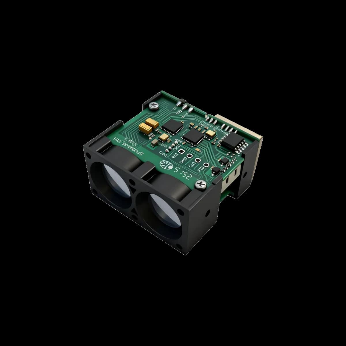
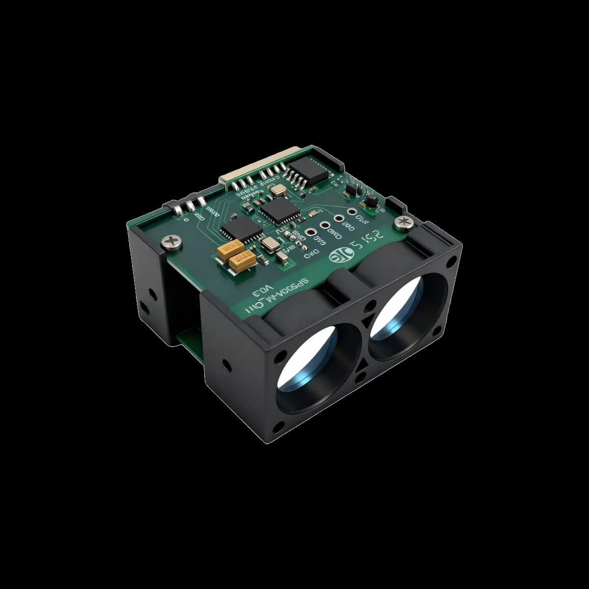
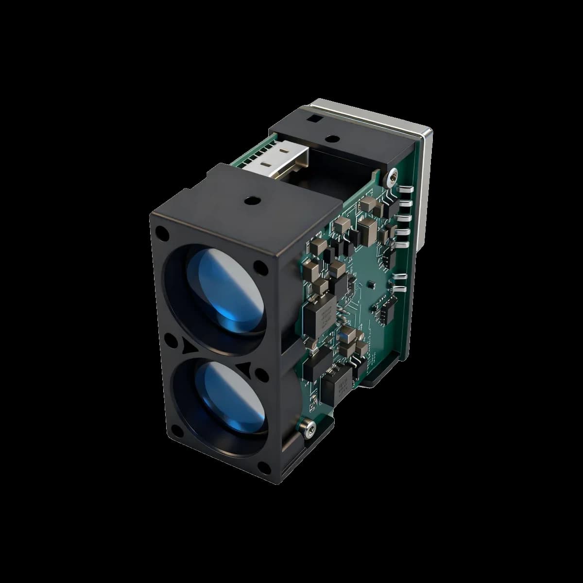
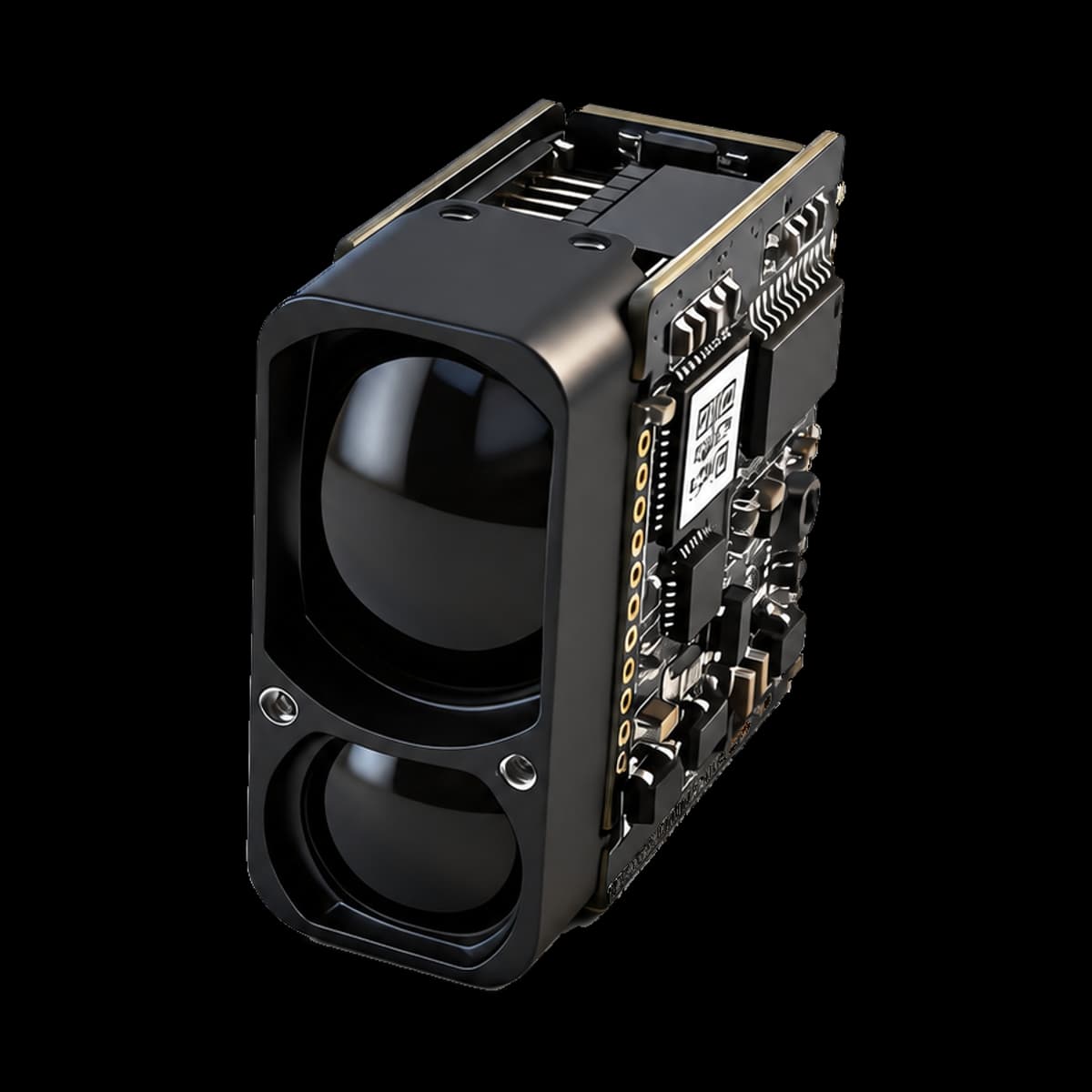
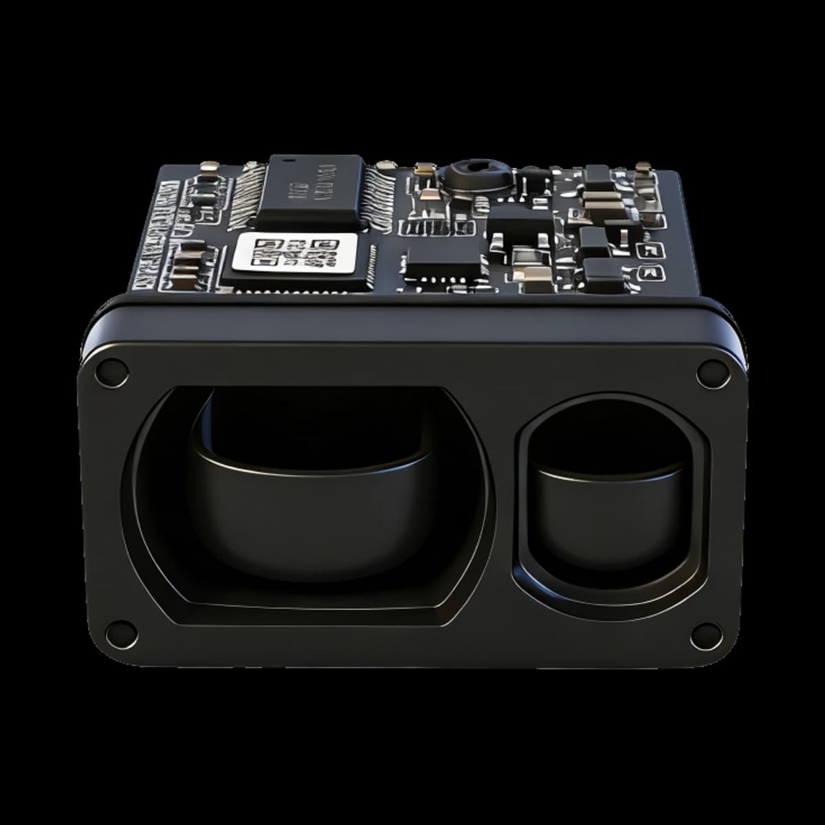
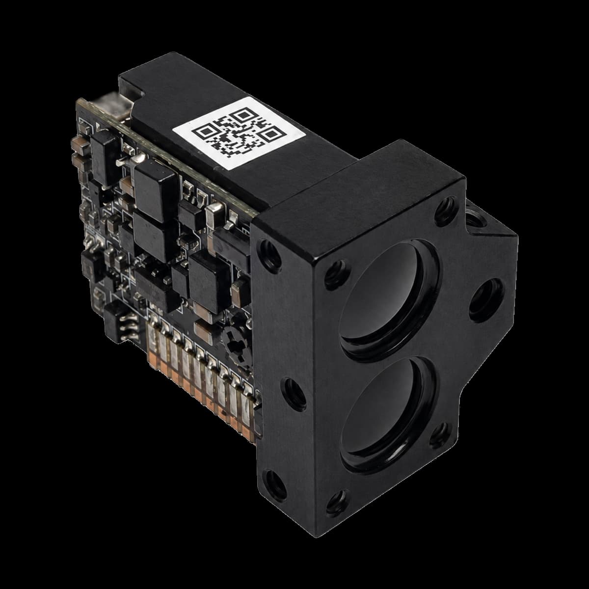
Detailed LRF600H Specifications
For a shuttle-vehicle positioning evaluation, target return and reporting behavior should be assessed together. The source links automatic rate selection to reflected-signal intensity; it does not establish high-rate operation at every distance. UART/IIC and a 9–36 V DC input provide the published electrical starting point for host review.
The 600 m model shares a 33 × 34 × 18 mm, 20 ± 2 g mechanical format with other H-series modules, but has its own target-dependent limits and long-range repeatability entry. Avoid deriving its performance from an adjacent model’s smaller error or treating a monitoring application as a certified collision-protection function.
Basic ranging performance
| Parameter | Value | Source condition |
|---|---|---|
| Measurement range | 0.05-600 m (90% reflectivity); 0.05-200 m (10% reflectivity) | The two source values remain bound to their stated target reflectivity. |
| Measurement frequency | 1 kHz or 50 Hz (automatically switched to match reflected-signal intensity) | Confirm against the controlled model document |
| Accuracy | ±10 cm (<10 m); 1% (≥10 m) | Confirm against the controlled model document |
| Repeatability | ±5 cm (<10 m); ±50 cm at 600 m | Confirm against the controlled model document |
| Ambient-light immunity | 100 klx | Confirm against the controlled model document |
| Reported resolution | 1 cm | Front-page feature statement; not an accuracy value |
Optical parameters
| Parameter | Value | Source condition |
|---|---|---|
| Central wavelength | 905 nm | Confirm against the controlled model document |
| Photobiological safety | Class 1 | Confirm against the controlled model document |
| Field of view | About 4 mrad | Confirm against the controlled model document |
| Wavelength for indication | N/A | Confirm against the controlled model document |
| Photobiological safety for indication | N/A | Confirm against the controlled model document |
Electrical and communication interface
| Parameter | Value | Source condition |
|---|---|---|
| Supply voltage | 9-36 V DC | Confirm against the controlled model document |
| Peak current | 100 mA | Confirm against the controlled model document |
| Average current | 55 mA | Confirm against the controlled model document |
| Average power consumption | 1.2 W | Confirm against the controlled model document |
| Communication interface | UART/IIC | Confirm against the controlled model document |
Mechanical and environmental
| Parameter | Value | Source condition |
|---|---|---|
| Protection level | N/A | Confirm against the controlled model document |
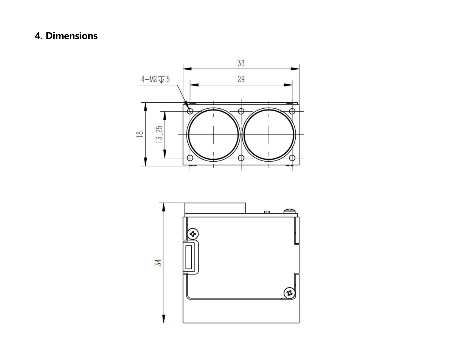
| Dimensions | 33 × 34 × 18 mm | Confirm against the controlled model document |
| Weight | 20 ± 2 g | Confirm against the controlled model document |
| Operating temperature | -20°C to +60°C | Confirm against the controlled model document |
| Wire specification | 1.25 mm, 5P, 50 cm stranded wires | Confirm against the controlled model document |
| Customization | Available in appearance / structure / output protocol | Confirm against the controlled model document |
Functional Description
The source states that 1 kHz or 50 Hz is selected automatically to match reflected-signal intensity.
The product is designed as a module for customer secondary development and integration.
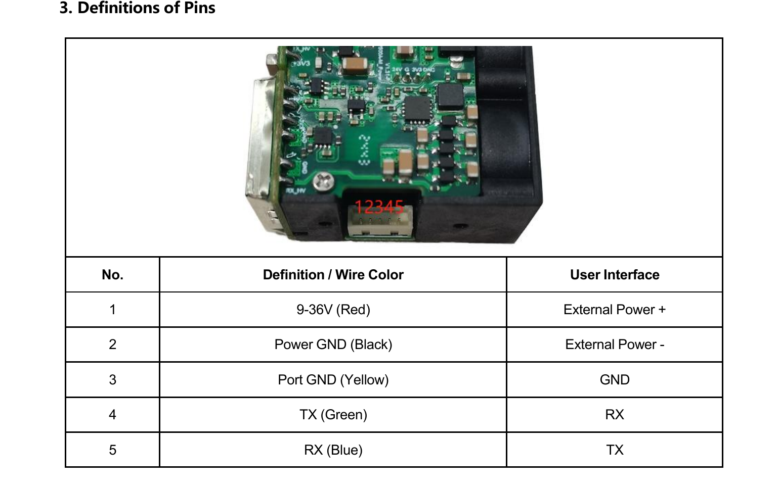
Electrical Interface Definition
Signal names and directions are transcribed from the model source.
| Pin | Signal | Source-stated function |
|---|---|---|
| 1 | 9-36V (red) | External power positive |
| 2 | Power GND (black) | External power negative |
| 3 | Port GND (yellow) | GND |
| 4 | TX (green) | Host RX |
| 5 | RX (blue) | Host TX |
Mechanical Dimension Drawing and Electrical Interface Diagram
These figures are extracted from the named model source without generative modification.
Direct Time-of-Flight Ranging
The LRF600H model document identifies the product as direct time of flight (DToF). It determines distance from the delay between an emitted optical pulse and the accepted return.
Real performance also depends on target reflectivity and area, incidence angle, atmospheric attenuation, receiver aperture, background light, detector response, timing thresholds and contamination of the optical path.
What the verified data supports
These are traceable design inputs, not unsupported superlatives or guaranteed field outcomes.
Performance envelope
Measurement range: 0.05-600 m (90% reflectivity); 0.05-200 m (10% reflectivity) · Accuracy: ±10 cm (<10 m); 1% (≥10 m)
Timing and output
Measurement frequency: 1 kHz or 50 Hz (automatically switched to match reflected-signal intensity) · Reported resolution: 1 cm · Repeatability: ±5 cm (<10 m); ±50 cm at 600 m
Electrical integration
Supply voltage: 9-36 V DC · Communication interface: UART/IIC · Average power consumption: 1.2 W
Mechanical integration
Dimensions: 33 × 34 × 18 mm · Weight: 20 ± 2 g · Operating temperature: -20°C to +60°C
Source-stated application context
Application labels indicate where the source proposes evaluation; they do not prove fitness without system testing.
- Shuttle-vehicle positioning and collision-avoidance monitoring
- Land-transport vehicle positioning and collision-avoidance monitoring
- Overhead-crane positioning and collision-avoidance monitoring
- Traffic-safety early warning
- Camera focusing
- Tower-crane distance detection
- Blade-encroachment detection
Confirm before selection
- Define target size, reflectivity, incidence angle and required detection probability.
- Reproduce sunlight, visibility, weather and optical-window conditions in acceptance testing.
- Verify voltage tolerance, peak current, grounding, interface levels, baud rate and connector revision.
- Separate accuracy, repeatability and displayed resolution in host requirements.
- Confirm mounting datum, boresight, field of view, enclosure sealing and thermal path.
- Assess accessible emission and labeling again after integration into the finished equipment.
Questions to resolve before design release
What makes the 600 m figure different from a general detection promise?
The specified upper limit is attached to a 90%-reflectivity target. The same source gives 200 m for 10% reflectivity. Actual vehicle-positioning targets must be represented in the evaluation, including their surface behavior and the installed optical geometry.
Can both published frequencies be obtained at once?
The source describes automatic selection between 1 kHz and 50 Hz according to reflected-signal intensity. It does not describe simultaneous dual streams. A required update rate should be evaluated at the distance and target condition relevant to the host task.
What repeatability is listed at 600 m?
The source separately lists ±50 cm repeatability at 600 m. Its accuracy entry remains 1% from 10 m upward. Repeatability is not a substitute for absolute measurement accuracy and must not be used to advertise an unsupported ±50 cm full-range accuracy.
Which electrical and mechanical facts are available for selection?
LRF600H is specified for 9–36 V DC with UART/IIC communication, a 33 × 34 × 18 mm package and 20 ± 2 g mass. The host power, connector, mounting and environmental arrangements should follow the model-specific record.
Does the source establish a safety-rated vehicle protection sensor?
No. It names positioning and collision-avoidance monitoring applications, including shuttle vehicles, but supplies no functional-safety certification through that wording. Treat the module as a distance-information component and assess the complete protective or control function separately.
Product evidence and general technical context
The model PDF controls product claims. Public references support only the general engineering explanations and must not be used to infer a missing model value.
- LRF600H Specification V2.0The named model’s stated specifications, conditions, interfaces and mechanical record.
- The Short-Range, High-Accuracy Compact Pulsed Laser Ranging SystemGeneral context for pulsed ranging, measurement error and target-dependent performance; not an ERDI model test.