

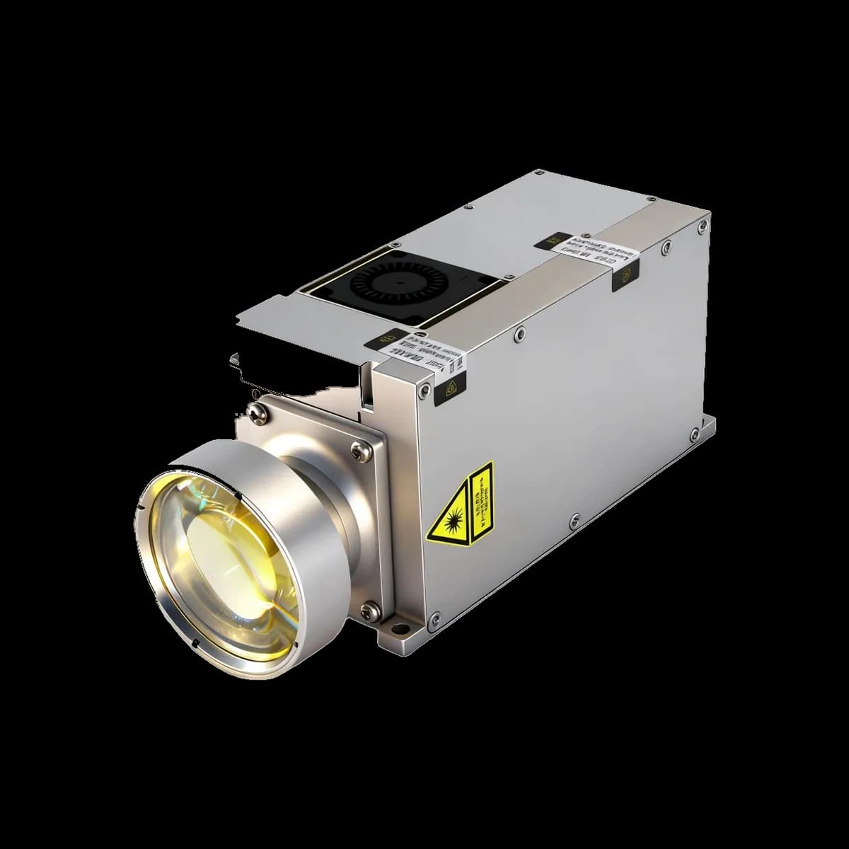
Detailed LR120K1 Specifications
The technical material below is retained for this model only. Do not transfer a range, pulse, interface, mechanical or safety value from another 1064 nm product.
Specifications
The tables below retain the supplied model record except for entries explicitly withheld after a comparison with the current model PDF. A value, option or condition from another model is not interchangeable. General explanations are separated from model-specific entries.
Source-review note
The source repeats a temperature value in place of the second temperature-row label. That entry is withheld until its property and condition are confirmed.
Current LR120K1 document — source checked 13 September 2026. On a small screen, swipe wide tables horizontally to read every column.
|
Functional Characteristics |
|
|
Provides laser ranging capability |
|
|
Supports long-cycle laser designator, short-cycle laser designator, and emergency laser designator modes. |
|
|
Includes built-in fixed frequency codes and supports online coding |
|
|
Supports receiver detector lockout via command control; the receiver is locked by default at power-on. |
|
|
Provides product temperature reporting. |
|
|
Supports both internal trigger and external trigger operating modes. |
|
|
Supports querying the laser emission count (cumulative count). |
|
|
Provides energy adjustment capability for product maintenance. |
|
|
Performance Parameters |
|
|
Operating wavelength |
1064 nm ± 3 nm |
|---|---|
|
Energy (minimum) |
≥ 120 mJ |
|
Energy levels |
50 mJ, 80 mJ, 120 mJ |
|
Energy ranges per level |
l 50–70 mJ l 80–100 mJ l ≥ 120 mJ |
|
Energy stability |
≤ ±10% per cycle (calculated after 2 s of laser designator) |
|
Effective range (large target) Laser ranging: |
a) ≥ 30 km (conditions: visibility ≥ 45 km, target reflectivity 0.2, relative humidity ≤ 80%) |
|
Ranging accuracy |
± 1 m |
|
Repetition rate |
Laser ranging: 1 Hz, 5 Hz laser designator: 20 Hz |
|
Valid measurement rate |
≥ 98% |
|
Pulse width |
15 ns ± 5 ns |
|
Beam divergence |
≤ 0.15 mrad |
|
Optical axis parallelism |
Parallelism between mounting datum plane and optical axis ≤ 0.3 mrad |
|
Operating modes |
a) Laser ranging: continuous operation ≥ 10 min, rest 5 min |
|
Laser designator coding |
a) 16 coding patterns |
|
Weight Requirements |
|
|
Total unit weight |
≤ 2 kg |
|
Weight consistency |
≤ 50 g |
|
Structural Requirements |
|
|
Overall dimensions |
≤ 75 mm (W) × 90 mm (H) × 220 mm (L) |
|
3D digital model requirements |
The external model shall be complete and comprehensive, including details such as screws, cable routing, and mating connectors. |
|
Load cable routing shall be included in the model design to avoid interference with the system. |
|
|
Electrical Interface |
|
|
DC input |
18 V–32 V, typical supply 28 V |
|
Average power consumption |
≤ 120 W @ 28 V |
|
Peak power consumption |
≤ 200 W @ 28 V |
|
Power-on inrush current |
≤ 5 A @ 28 V |
|
Digital ground, power ground, and mechanical housing shall be electrically isolated. |
|
|
Environmental Adaptability Requirements |
|
|
Operating Temperature |
−40 °C to +60 °C |
| Temperature entry — source label unresolved | Withheld pending a corrected, controlled model specification. See the source-review note above. |
|
Vibration |
|
|
Equipment vibration testing shall be conducted in accordance with MIL-STD-810G, Laboratory Environmental Test Methods for Military Equipment. |
|
|
Vibration conditions |
8.2 Hz – 86.4 Hz: 0.1 g²/Hz 156.4 Hz – 172.8 Hz: 0.025 g²/Hz 234.6 Hz – 259.2 Hz: 0.006 g²/Hz Other frequency points within 15 Hz – 2000 Hz: acceleration spectral density of 0.004 g²/Hz Vibration shall be applied along the X, Y, and Z axes, 15 minutes per axis. |
|
Shock |
|
|
Vertical axis |
≥ 20 g |
|
Lateral and longitudinal axes |
≥ 15 g |
|
Pulse duration |
11 ms |
|
3 axes, 2 directions per axis, 18 shocks in total |
|
|
Shock testing shall be conducted in accordance with MIL-STD-810G, Laboratory Environmental Test Methods for Military Equipment. |
|
|
Pin |
Definition |
Description |
|---|---|---|
|
A1 |
+28 V Input Power |
|
|
A2 |
+28 V Input Ground |
|
|
4 |
Designator Serial TX+ (from designator to EO platform +) |
|
|
11 |
Designator Serial RX− (from EO platform to designator −) |
|
|
9 |
Designator Serial TX− (from designator to EO platform −) |
|
|
2 |
Designator Serial RX+ (from EO platform to designator +) |
|
|
8 |
Designator Serial Ground |
|
|
14 |
External Sync RS-422 RX+ |
RS-422 level input |
|
12 |
External Sync RS-422 RX− |
|
|
13 |
External Sync RS-422 GND |
|
|
5 |
CAN H |
Isolated CAN 2.0B, 1 Mbps, no termination resistor installed |
|
6 |
CAN L |
|
|
7 |
CAN GND |
|
|
B1 |
Laser Designation Sync Signal Output TX+ |
RS-422 level output, active low, pulse width 10 μs |
|
B2 |
Laser Designation Sync Signal Output TX− |
|
|
3 |
Laser Designation Sync Signal Output GND |
Technical drawings
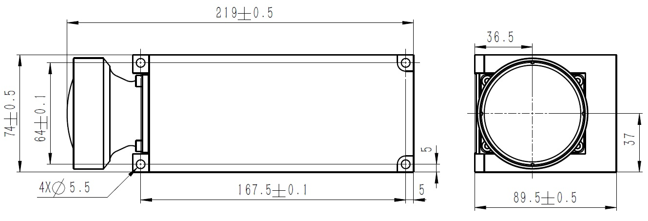
Evidence status: published data is not a substitute for the ordered revision, a serial-number test report or a laser-classification report. A standard mentioned in a table is not proof of third-party certification.
Model-specific conditions and limits
Conditions are retained only when the source states them. They are not reconstructed from a nominal range or wavelength.
Operating conditions
Read the value together with its qualifier
A minimum, maximum, typical value and tolerance are different kinds of statement. “≥” is a lower bound and “≤” is an upper bound; neither is an exact measurement. A nominal value without tolerance does not establish a tolerance. Preserve the units and the condition printed beside every entry.
Keep operating modes separate
If the original table lists more than one operating mode, each rate, duration and stability statement belongs to its stated mode. This page does not combine the most favorable entries into a new operating specification. A published duration is not evidence of unrestricted continuous operation.
Environment and document revision
Storage limits describe a non-operating condition and must not be substituted for powered-operation limits. A test-standard name without the method, severity, configuration and outcome is an incomplete qualification record. Request the relevant report for the exact supplied revision; do not describe a reference to a standard as a blanket certification.
Safety review
1064 nm is outside normal visual perception. A beam that cannot be seen can still be hazardous; brightness or a camera image is not a safety measurement. Laser safety assessment must address the complete product and its accessible emission, not only the source wavelength. IEC 60825-1:2014 — Safety of laser products; FDA — Frequently Asked Questions About Lasers.
Pulsed Time-of-Flight Ranging
Technical principle
Laser emission: a high-level overview
A laser combines an energized gain medium with optical feedback to produce stimulated emission. Solid-state lasers use a solid host for the active species. The wavelength name alone does not identify a particular host material, pump wavelength or cavity construction, so this page does not infer those internal parts for LR120K1. FDA — Frequently Asked Questions About Lasers.
What a pulsed-source specification describes
Pulse energy describes energy in one optical pulse. Pulse duration describes its temporal extent under a stated width convention. Repetition rate describes how often pulses occur. These quantities must not be substituted for each other: an energy specification is not a power specification, and a rate does not describe a waveform. Electrical input power and optical output also refer to different quantities.
Beam size and angular spread are different measurements
A beam diameter applies at a specified measurement plane. Divergence describes angular spreading rather than diameter at one location. Different width definitions and full-angle versus half-angle conventions can give different numerical descriptions of the same beam. Where the model record does not identify its convention, the comparison remains incomplete. ISO 11146-1:2021 — Beam-width, divergence and propagation measurement terminology.
Accuracy, resolution and stability are separate terms
Resolution describes the reported increment or discrimination scale; accuracy concerns the difference between a measurement and a reference. Stability concerns variation over an interval or set of conditions. A small displayed increment does not by itself establish small error, and one stability metric does not establish another. The original table’s labels and qualifiers remain important even when two entries share a numerical value.
Physical explanation versus product evidence
A scientific paper can explain a phenomenon without testing this product. Its measured output, material recipe, internal geometry or performance cannot be transferred to LR120K1. A manufacturer's published record, a unit test, a qualification report and an independent standard each answer a different question. The references below are explicitly identified by that role.
Invisible radiation and responsible documentation
Eye and skin hazards depend on exposure, not on whether an observer sees a spot. A product page is not a safe operating procedure. Applicable controls and personnel responsibilities require a qualified safety review, and the product must retain its warnings and approved instructions. OSHA — Laser Hazards.
Pulse energy describes emitted energy per pulse; its effect cannot be separated from pulse width, divergence, optical losses, receiver threshold and the stated target/atmosphere conditions. It is not a substitute for a model-specific near- or long-range acceptance test.
Source-stated application context
Application labels indicate evaluation context, not automatic fitness for a finished system.
The controlled LR120K1 PDF describes artillery fire support, laser-guided munitions, and vehicle- or shipborne EO/IR platforms.
This context is bound only to the controlled LR120K1 document; end-system suitability and acceptance remain subject to engineering review.
Confirm short- and long-distance acceptance conditions
- Define minimum distance, target material, reflectance, size and incidence angle.
- Check receiver recovery, optical-axis overlap and strong-return handling at the intended near limit.
- Verify supply tolerance, peak current, grounding, interface levels, connector and timing with the ordered revision.
- For long-distance acceptance, state target geometry, visibility, weather, background and required detection probability.
- Test with the installed window, boresight, field of view, enclosure and thermal path rather than a bare module alone.
- Evaluate accessible emission, labels and failure conditions again for the finished laser product under IEC 60825-1.
Questions to resolve before design release
FAQ
Is 1064 nm visible to the eye?
It is infrared rather than ordinary visible light. Absence of a visible beam does not indicate absence of emission or hazard. Do not use visual appearance as an exposure assessment.
Does the wavelength determine the laser class?
No. Product classification depends on accessible emission and the relevant assessment conditions. The wavelength is one input, not a classification certificate.
Does pulse energy describe electrical consumption?
No. Pulse energy is optical energy per pulse. Supply consumption is an electrical quantity and belongs to its own operating condition in the model documentation.
Are accuracy and resolution interchangeable?
No. A reporting increment is not a bound on measurement error. Read each field under its own definition and test conditions.
Can full-angle and half-angle divergence be compared directly?
Not without identifying the convention. If the released record does not state it, request the measurement definition rather than silently choosing one.
Can the best figures from different operating modes be combined?
No. A rate, duration or stability condition belongs to the mode to which it is assigned. Combining unrelated conditions creates a new, unsupported specification.
Does a cited standard prove certification?
No. A citation identifies a framework or test method. Certification or completed qualification needs the relevant report and an explicit statement of the assessed product configuration.
What does a “typical” value mean here?
It describes the source record’s representative value, not a newly guaranteed upper or lower limit. A typical entry must remain labeled typical.
Can storage temperature be used as the operating range?
No. Non-operating storage and powered operation are different states. Preserve both entries and their qualifiers.
Does a reference paper establish this product’s internal material or design?
No. General laser physics is not a bill of materials. Internal materials and construction require a controlled model source.
What should happen when a source unit or field is incomplete?
Leave the uncertainty visible and obtain a corrected controlled document. Do not infer a missing unit, test condition or option from the product name.
Where are the sources for this page?
The Technical Downloads area contains the model document. The bibliography separates product evidence from general standards and safety information; neither replaces a unit-specific test record.
Product evidence and general technical context
The model PDF controls model claims. Public references below explain general engineering principles only.
References
Model evidence
LR120K1 — current model document. Use the ordered revision for configuration. The previous table was compared with the current document; conflicting or incomplete entries remain visibly unresolved rather than inferred. This comparison is not a full manual validation or a product test.
General definitions and safety sources
- IEC 60825-1:2014 — Safety of laser products — classification framework, not a declaration of this product’s class.
- ISO 11146-1:2021 — Beam-width, divergence and propagation measurement terminology — measurement terminology, not a product test.
- FDA — Frequently Asked Questions About Lasers — general laser explanation and hazard information, not product performance evidence.
- OSHA — Laser Hazards — general laser explanation and hazard information, not product performance evidence.
References reviewed 13 September 2026.
- ERDI LR120K1 model PDFModel-specific technical evidence.
- System Design of a Pulsed Laser RangefinderOptical Engineering 30(3), 1991 - link budget, background, noise, detection and range error.
- The Short-Range, High-Accuracy Compact Pulsed Laser Ranging SystemSensors 22(6), 2146, 2022 - pulsed-ToF equation, timing error, reflectivity and temperature effects.
- Laser system range calculations and the Lambert W functionApplied Optics 48(4), B1-B7, 2009 - range performance versus atmospheric transmission, target and system parameters, and threshold SNR; its 1.06 µm example is general context, not ERDI model data.
- Monostatic all-fiber rangefinder systemApplied Optics 54(25), 7687-7694, 2015 - a measured case study of shared-aperture geometry and receiver-recovery loss; it does not establish an ERDI model limit.
- Light Transmission in Fog: The Influence of Wavelength on the Extinction CoefficientApplied Sciences 9(14), 2843, 2019 - measured and modeled wavelength-dependent fog attenuation.
- IEC 60825-1:2014Laser-product classification and accessible-emission requirements; final equipment requires system-level assessment.