

Distance, Attitude, and Relative 3D Measurement
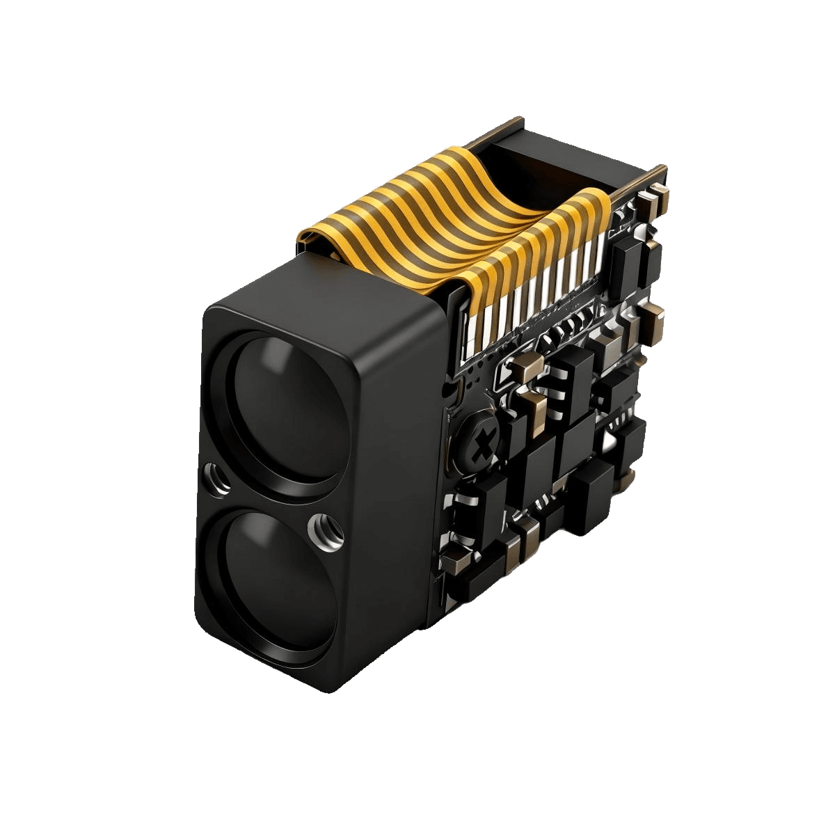
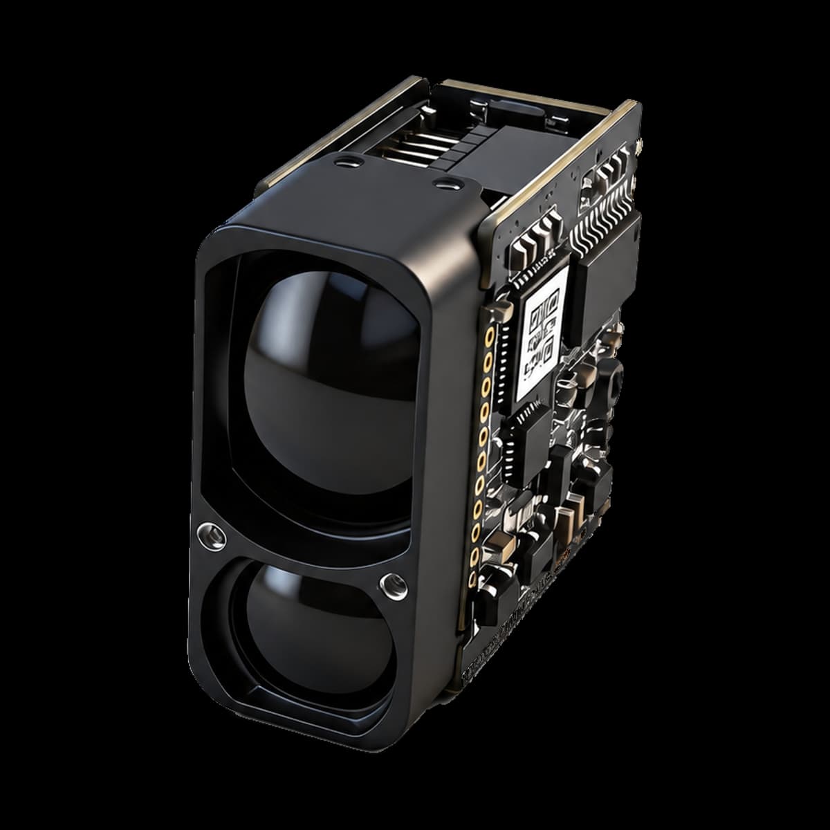
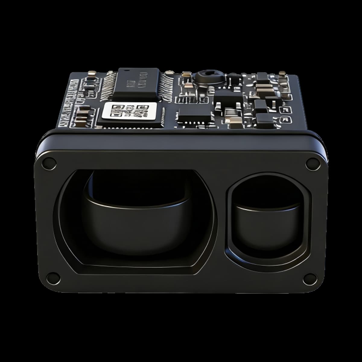
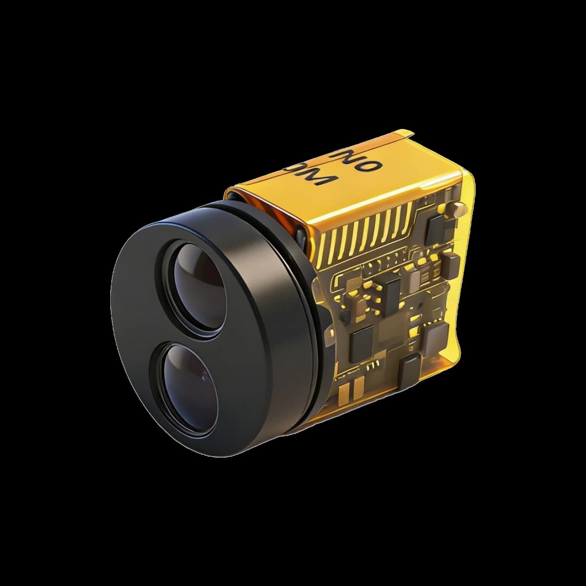
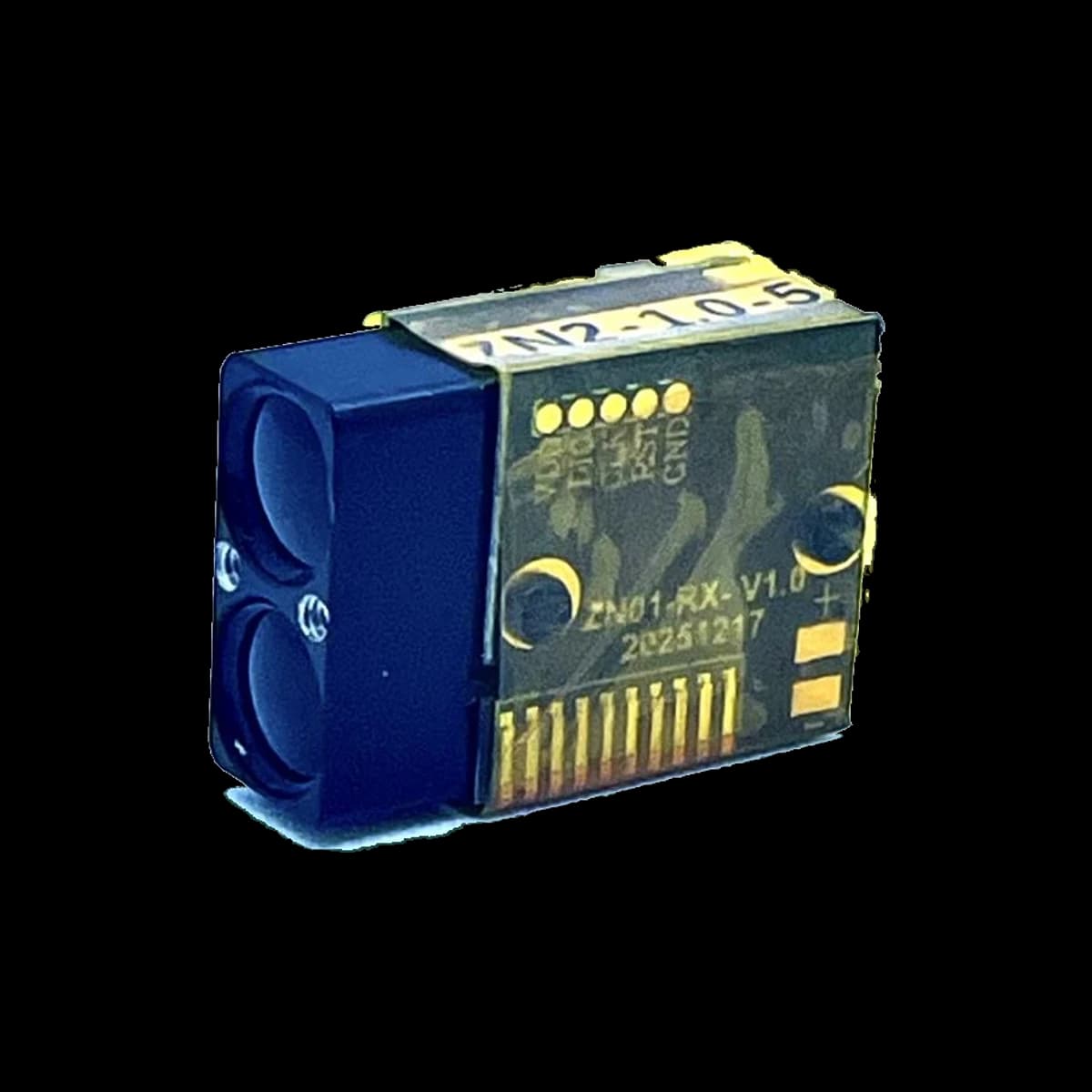
The SPD1200ZG combines compact 905 nm pulsed laser ranging with integrated inertial angle sensing for OEM systems that need distance, attitude, and relative three-dimensional point-to-point measurement in one lightweight module.
It supports single and continuous ranging, configurable angle reporting, and UART-TTL communication for host integration.
Nominal body dimensions are 7.2 × 14.7 × 22.3 mm and weight is no more than 5 g; the complete installation envelope is governed by the current mechanical drawing.
SPAD-based pulsed ranging
905 ± 5 nm direct time-of-flight ranging with single-photon reception for weak optical returns.
0.1–1200 m specified range
Rated with visibility ≥10 km, humidity ≤60%, and a building target.
Integrated six-axis inertial sensing
Configurable roll, pitch, and relative yaw/heading reporting for angle-enabled builds.
Relative 3D point-to-point measurement
Combines local range and angle information for target-point coordinates and spatial separation.
Compact OEM package
Nominal body size 7.2 × 14.7 × 22.3 mm, 6061 aluminum-alloy housing, and weight ≤5 g.
Flexible host integration
UART-TTL communication, 115200 bps default baud rate, and a 2–10 Hz measurement update rate.
SPD1200ZG Specifications
Read each performance value with its stated target, environmental, operating, and installation conditions.
Optical and ranging
| Parameter | Value | Conditions / notes |
|---|---|---|
| Laser wavelength | 905 ± 5 nm | — |
| Beam divergence | <6 mrad; small beam spot | — |
| Optical element | Aspheric lens | — |
| Receiver aperture | Ø6.5 mm | — |
| Measurement range | 0.1–1200 m | Visibility ≥10 km; humidity ≤60%; building target |
| Ranging accuracy | ±0.5 m at d ≤100 m; ±(0.5 m + 0.0007d) for 100 m < d <1200 m | — |
| Measurement update rate | 2–10 Hz | — |
| Measurement success rate | ≥98% | — |
| False alarm rate | ≤1% | — |
| Laser safety class | IEC Class 1 | — |
Electrical and environmental
| Parameter | Value | Conditions / notes |
|---|---|---|
| Communication interface | UART-TTL; customizable | — |
| Default baud rate | 115200 bps | — |
| Supply voltage | 3.3–5 V | — |
| Startup time | ≤200 ms | — |
| Peak startup current | ≤200 mA | — |
| Standby power consumption | ≤0.3 W | — |
| Average power consumption | ≤0.7 W | — |
| Operating temperature | −20 to +60 °C | — |
| Storage temperature | −30 to +70 °C | — |
| Ingress protection | IP67 within the lens cavity | — |
Mechanical
| Parameter | Value | Conditions / notes |
|---|---|---|
| Nominal module body | 7.2 × 14.7 × 22.3 mm; rectangular | The complete installation envelope includes protruding features; use the current mechanical drawing. |
| Housing material | 6061 aluminum alloy | — |
| Weight | ≤5 g | — |
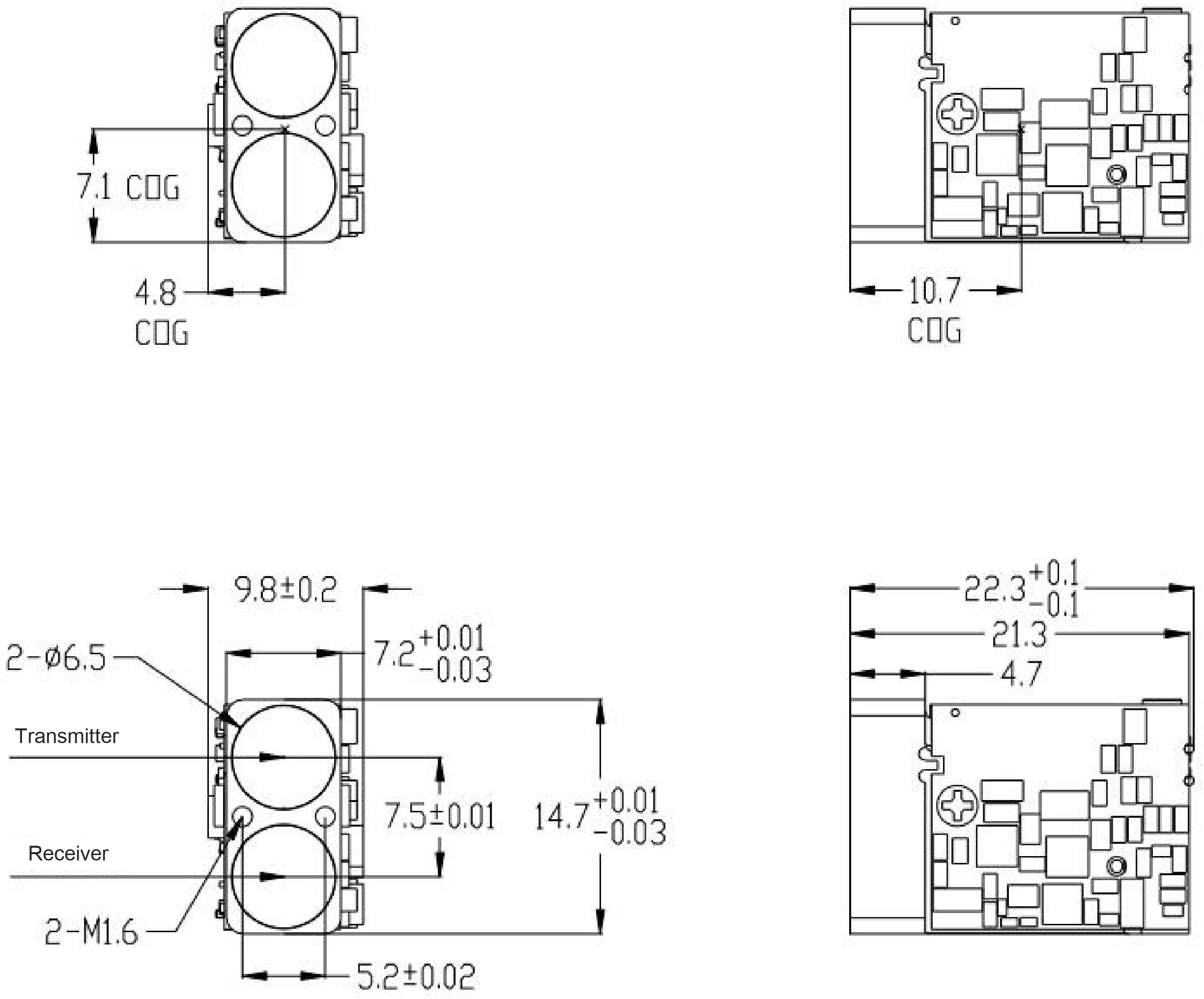
| Width across protruding features shown in drawing | 9.8 ± 0.2 mm | — |
| Core width shown in drawing | 7.2 +0.01/−0.03 mm | — |
| Height shown in drawing | 14.7 +0.01/−0.03 mm | — |
| Axial dimensions shown in drawing | 22.3 ± 0.1 mm and 21.3 mm | — |
| Mounting features shown in drawing | 2 × M1.6; 5.2 ± 0.02 mm spacing feature | — |
| Optical features shown in drawing | 2 × Ø6.5; 7.5 ± 0.01 mm spacing feature | — |
| Center-of-gravity coordinates shown in drawing | 7.1, 4.8, 10.7 | — |
Inertial measurement
| Parameter | Value | Conditions / notes |
|---|---|---|
| Roll range, X axis | ±180° | — |
| Pitch range, Y axis | ±90° | — |
| Yaw range, Z axis | ±180° | — |
| X/Y tilt accuracy | 0.3° | — |
| Z-axis heading accuracy | ≤0.75° within a 10 s dynamic measurement interval | Integration error accumulates during motion; this is relative heading, not an absolute north reference. |
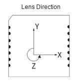
| Axis orientation | Y axis points toward the lenses | — |
3D point-to-point — radial error
| Parameter | Value | Conditions / notes |
|---|---|---|
| d ≤500 m | ±1 m | Distance variable d follows the product specification. |
| 500 m < d <1200 m | ±(1 m + 0.001d) | Distance variable d follows the product specification. |
3D point-to-point — static maximum absolute error
| Parameter | Value | Conditions / notes |
|---|---|---|
| <100 m | ≤1 m | — |
| 100–500 m | ≤3 m | — |
| 500–1000 m | ≤5 m | — |
3D point-to-point — dynamic maximum absolute error
| Parameter | Value | Conditions / notes |
|---|---|---|
| <50 m | ≤1 m | — |
| 50–100 m | ≤3 m | — |
| 100–500 m | ≤6 m | — |
| 500–1000 m | ≤10 m | — |
Pulsed Time of Flight and SPAD Reception
Pulsed Time-of-Flight Ranging
The module transmits a short optical pulse and detects light reflected from the target. If the measured round-trip transit time is Δt, the geometric one-way range is R = cΔt / 2. The factor of two accounts for the outbound and return paths.
Timing resolution, pulse width, receiver bandwidth, target reflectivity, incidence angle, background illumination, and beam divergence influence practical ranging performance. [1]
SPAD-Based Single-Photon Reception
This SPD1200ZG configuration uses SPAD-based single-photon reception. A single-photon avalanche diode can register individual photon events.
In direct-ToF systems generally, repeated photon detections may be organized in time bins so that a return concentrated around one delay can be distinguished from background detections. Ambient illumination, detector dead time, pile-up, and finite timing resources are recognized constraints. [2] [3]
The standard customer interface reports processed measurements; it does not claim access to raw photon timing data or a particular internal processing algorithm.
Six-Axis Inertial Measurement Explained
A conventional six-axis IMU comprises three orthogonal gyroscope angular-rate channels and three orthogonal accelerometer specific-force channels. Six-axis describes six sensing channels, not six independent rotational axes. [6]
Angle reporting is configurable and does not imply that the standard customer interface exposes all six raw sensor channels. Available outputs are defined by the configuration-matched interface protocol.
For a fixed single-axis rotation, the conceptual relationship is θ(t) = θ₀ + ∫ω(t)dt. Angular-rate bias and noise create accumulated angle drift. Three-axis attitude estimation requires an appropriate coordinate convention. [5]
| Measurement | Rating |
|---|---|
| Roll | ±180° about the X axis |
| Pitch | ±90° about the Y axis |
| Relative yaw / heading | ±180° about the Z axis |
| X/Y tilt accuracy | 0.3° |
| Z-axis heading accuracy | ≤0.75° within a 10 s dynamic measurement interval |
Integration error accumulates during motion. This is relative heading, not an absolute north-referenced compass specification.
Coordinate Convention
Use the current manual's X/Y/Z convention when interpreting angle-enabled output.
Relative 3D Point-to-Point Measurement
An angle-enabled configuration can acquire range and angular information for point A and point B, then report their relative spatial separation in one local coordinate frame.
Conceptually, straight-line separation follows DAB = ||pB − pA||. Range uncertainty, angular uncertainty, alignment, zeroing, and motion at both observations propagate into the result. [8]
Radial error
| Distance band | Error |
|---|---|
| d ≤500 m | ±1 m |
| 500 m < d <1200 m | ±(1 m + 0.001d) |
Static maximum absolute error
| Distance band | Error |
|---|---|
| <100 m | ≤1 m |
| 100–500 m | ≤3 m |
| 500–1000 m | ≤5 m |
Dynamic maximum absolute error
| Distance band | Error |
|---|---|
| <50 m | ≤1 m |
| 50–100 m | ≤3 m |
| 100–500 m | ≤6 m |
| 500–1000 m | ≤10 m |
Body Size and Complete Installation Envelope
The nominal 7.2 × 14.7 × 22.3 mm body size does not include every protruding feature. Use the complete drawing and its tolerances for installation.
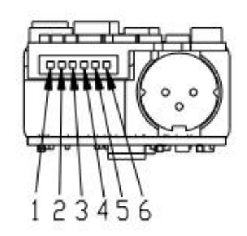
Six-Pin Connection
The 3.3–5 V high-level range applies to the SW-SHOT input. It is not a blanket voltage rating for the UART pins.
| Pin | Signal | Function |
|---|---|---|
| 1 | GND | Power-supply ground |
| 2 | VCC | Positive supply input |
| 3 | IO (reserved) | Reserved for expansion |
| 4 | TXD | Module-to-host signal output |
| 5 | RXD | Host-to-module signal input |
| 6 | SW-SHOT | Function enable, active high; high-level input range 3.3–5 V |
Single, Continuous, and Angle-Enabled Operation
Single measurement
Initiates one target-distance measurement. For a low-reflectivity target, the module automatically repeats the measurement until it obtains a stable reading, then reports the result through the serial interface.
Continuous measurement
Repeated distance measurement at a 2–10 Hz measurement update rate.
Configurable angle measurement
Angle-enabled configurations report pitch, roll, and relative yaw/heading using the matching interface protocol.
Compact Distance and Attitude Sensing
- Handheld and fixed optical observation instruments
- Night-vision and thermal-imaging accessories
- Telescopic observation and outdoor measurement equipment
- Perimeter and facility monitoring
- Power-infrastructure and railway inspection
- Smart water-management and civil-engineering measurement
- Communications and aviation support equipment
- Industrial UAV ranging and electro-optical payload integration, subject to system-level validation
- Outdoor recreation and field measurement tools
Validate the complete system with representative targets, lighting, temperature, motion, mounting, and the final protective window.
From Bench Test to Installed System
- Size the supply for startup current and use a common signal ground. The 3.3–5 V supply range is not a blanket UART-pin voltage rating.
- Select a protective window with suitable transmission near 905 nm, minimize transmit-to-receive reflections, and test the assembled window for false near returns.
- Validate dark, small, angled, wet, and partially obscured targets at the required distance and under representative lighting.
- Assess visibility, sunlight, condensation, dust, temperature, mechanical alignment, and motion in the complete installation.
- Use the configuration-matched interface protocol for packet fields, scaling, and checksum handling.
- Assess laser safety for the finished equipment, including added optics, controls, access, labeling, and operating conditions.
SPD1200ZG: Frequently Asked Questions
What does 905 nm pulsed time-of-flight ranging mean?
The module emits a short pulse centered at 905 ± 5 nm and measures the light's round-trip transit time. Range follows R = cΔt/2, because the pulse travels to the target and back. [1]
What is the benefit of SPAD-based single-photon reception?
A SPAD can register individual photon events, which supports reception of weak optical returns. A published direct-ToF SPAD implementation demonstrates how repeated arrival-time events can be accumulated in time bins for range estimation under varying reflectivity and background conditions. [3]
Does the 0.1–1200 m range apply to every target and environment?
No. The 1200 m rating uses visibility ≥10 km, humidity ≤60%, and a building target. Target reflectivity, target size within the beam footprint, incidence angle, haze, rain, dust, and strong background illumination can change practical measurement margin. [1] [4]
How should the ranging-accuracy value be interpreted?
For line-of-sight range d in meters, accuracy is ±0.5 m at d ≤100 m and ±(0.5 m + 0.0007d) for 100 m < d <1200 m. This is separate from resolution, repeatability, and 3D point-to-point error.
Why can daylight and low target reflectivity affect a measurement?
The receiver must separate returned signal events from background events and detector noise. Bright ambient light increases unrelated detections, while low reflectivity reduces the desired return, lowering signal-to-background ratio. [2] [4]
What does the integrated six-axis inertial function add?
A conventional six-axis IMU has three orthogonal gyroscope angular-rate channels and three orthogonal accelerometer specific-force channels; it does not mean six independent rotation axes. In an angle-enabled configuration, the module adds roll, pitch, and relative yaw/heading information to the range measurement. The standard interface does not necessarily expose all six raw channels. [6]
Is the Z-axis heading an absolute compass heading?
No. It is a relative inertial heading/yaw measurement. The specified accuracy is ≤0.75° within a 10 s dynamic measurement interval, and integration error accumulates during motion. [5]
Does the 0.3° X/Y tilt value apply during arbitrary motion?
The specified X/Y tilt-accuracy value is 0.3°. Gravity/acceleration-derived tilt is most reliable under static or quasi-static conditions, while dynamic acceleration can affect inferred tilt. Validate the module in the intended motion profile and mounting arrangement. [7]
How is the distance between point A and point B determined?
An angle-enabled configuration acquires range and angle information for both points in one local coordinate frame, then reports their straight-line spatial separation. In general geometry, this is the Euclidean distance between the two point vectors. [8]
Why is point-to-point error different from ranging accuracy?
Line-of-sight range is one scalar measurement. A point-to-point result combines two observations and their angular estimates, so range error, angle error, alignment, zeroing, and motion all contribute. [8]
What communication interface and update rate are available?
The module supports UART-TTL and a 2–10 Hz measurement update rate. The default baud rate is 115200 bps, interface customization is available, and the supply range is 3.3–5 V.
Where can I obtain the serial packet definitions?
Use the interface protocol supplied for the ordered firmware and configuration. The matching document defines the applicable packet fields, value scaling, and checksum handling for host implementation.
What lead time applies to my quantity?
In stock. Dispatch is within 7 working days for 1–30 pcs, 30 working days for 31–100 pcs, and 45 working days for 101 pcs or more, counted from payment confirmation. Shipping is included to the shipping address you enter.
Product Documentation and Technical Literature
The current SPD1200ZG manual defines product specifications. The independent references explain general principles and do not replace the module's stated ratings or conditions.
- SPD1200ZG User Manual EN — Public edition 2026-09-06Current model specifications, dimensions, electrical interface, and communication information.
- [1] Performance Analysis of Next-Generation LADAR for Manufacturing, Construction, and MobilityNIST technical report covering pulsed laser ranging, round-trip time of flight, timing resolution, and practical range influences; it is not SPD1200ZG performance data.
- [2] Statistical Modelling of SPADs for Time-of-Flight LiDARPeer-reviewed SPAD ToF modeling covering photon detection, ambient background, detector dead time, and pile-up; it does not identify the module’s internal acquisition architecture.
- [3] A Reconfigurable 3-D-Stacked SPAD Imager With In-Pixel Histogramming for Flash LIDAR or High-Speed Time-of-Flight ImagingPeer-reviewed direct-ToF SPAD implementation demonstrating time-bin photon accumulation under varying reflectivity and solar background; its chip and algorithm are not module specifications.
- [4] A Few Photons Among Many: Unmixing Signal and Noise for Photon-Efficient Active ImagingPeer-reviewed photon-efficient imaging research explaining temporally concentrated returns, distributed background events, and signal-to-background effects; its algorithm is not a module guarantee.
- [5] An Introduction to Inertial NavigationUniversity technical report explaining MEMS angular-rate measurement, integration, bias, noise, and orientation drift; example results are not module ratings.
- [6] Using Inertial Sensors for Position and Orientation EstimationOpen inertial-sensing tutorial covering three-axis gyroscope and accelerometer measurements, orientation estimation, and integration drift; it does not define the module’s estimator.
- [7] Sensor Fusion for Structural Tilt Estimation Using an Acceleration-Based Tilt Sensor and a GyroscopePeer-reviewed research covering gravity-based tilt, dynamic acceleration effects, and complementary angular-rate sensing; it does not validate the module’s 0.3° rating.
- [8] Rigorous Error Propagation for Terrestrial Laser Scanning With Application to Snow Volume UncertaintyPeer-reviewed error-propagation research for range-and-angle point coordinates and derived distances; results from the studied scanner are not module performance data.