

From Erbium Glass to Integrated Laser Ranging Hardware
ERDI TECH LTD develops the 1535 nm transmitter chain from active-medium and coating specifications through microchip-laser packaging, ranging electronics and OEM module verification. The wider platform includes 905 nm distance sensors and 1064 nm ranging and designation hardware.
- Active medium
- Er:Yb glass and coating control
- Laser sources
- 1535 nm pulsed microchip platforms
- Ranging
- 905 nm and 1535 nm OEM modules
- System hardware
- 1064 nm ranging and designation
Performance Is Built Across the Complete Optical Path
A rangefinder is not defined by pulse energy or nominal distance alone. Stable field behavior depends on how the gain medium, resonator, coatings, transmitter, receiver, timing electronics, mechanics and firmware are designed and verified together.
Er:Yb Glass and Optical Coatings
The active medium establishes pump absorption, gain, loss and thermal margin. Coating requirements are defined by wavelength, angle, polarization, optical fluence and service environment; approved lots remain linked to the build record.
1535 nm Q-Switched Laser Source
Pump diode, Er:Yb gain glass, passive Q-switch, resonator output coupling, drive pulse and thermal path are treated as one oscillator. Pulse width, divergence, timing and package stability matter alongside pulse energy.
Transmit and Receive Optics
Beam shaping, transmitter aperture, receiver field of view, spectral filtering and InGaAs detection establish the usable link budget. Window, contamination and boresight are part of the system, not packaging details.
Timing, Detection and Data
Pulse drive, the time base, receiver front end, detection threshold and echo-selection logic turn a reflected pulse into range data. Firmware defines measurement modes, target reports, status handling and serial-link behavior.
OEM Module Integration
Mechanical datums, connector choice, power, TTL, UART or RS-422 communication, heat rejection and acceptance records are controlled at model and configuration level before release.
1064 nm Ranging and Designation Hardware
A 1064 nm rangefinder/designator is not a scaled-up 1535 nm module. Higher pulse energy, coded operation, pointing stability, thermal loading, accessible-emission controls and host-system interlocks require a distinct architecture and acceptance plan.
View 1064 nm platformsInside Assembly, Alignment and Verification
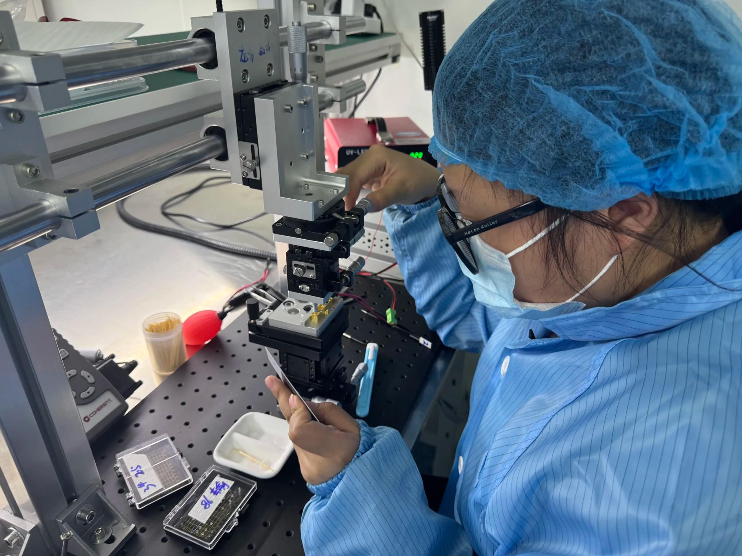
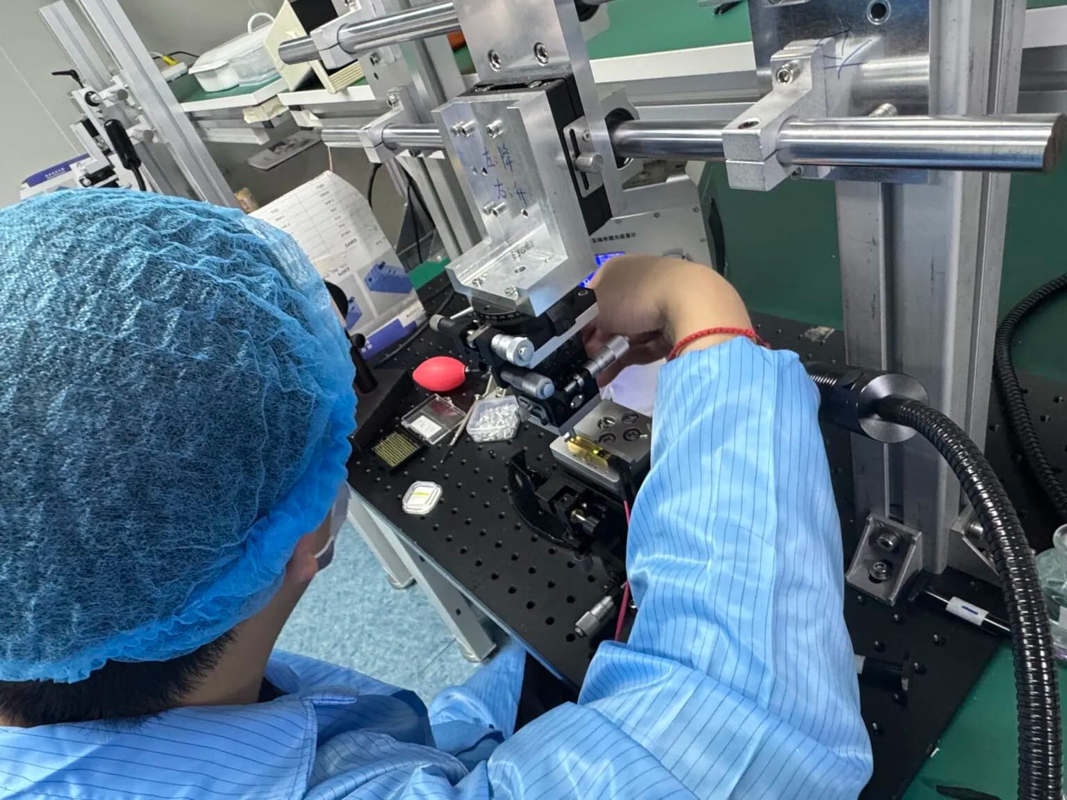
This 84-second documentary follows component preparation, electrical setup, optical alignment, functional verification and cross-disciplinary engineering review inside ERDI.
The Chain, Seen at Product Level
These model-specific films connect the source, eye-safe ranging and 1064 nm system-hardware stages to products that integration teams can review in detail.
MINI-100
1535 nm microchip erbium-glass laser package for compact transmitter integration.
Open product recordWatch product videoLRF0815C
8 km-class 1535 nm OEM rangefinder architecture for defined target and visibility conditions.
Open product recordWatch product videoLDR20K1
Compact ranging and coded-designation hardware with a model-specific control interface.
Open product recordWatch product videoResearch Converts an Application Into a Controlled Design
ERDI reviews optics, electronics, firmware, mechanics and verification together. Compact size and low mass are achieved by removing interface conflict and redundant volume, while keeping thermal, alignment and manufacturing margins visible.
- 01Application definitionTarget, atmosphere, range, update rate, host optics and acceptance criteria
- 02Optical link budgetTransmitter, beam, target return, aperture, detector and noise margin
- 03Electronics and firmwarePower, timing, receiver chain, mode logic, interface and fault behavior
- 04Optomechanical packagingDatums, boresight, thermal path, connector, window and service envelope
- 05Prototype verificationMeasured behavior compared with the controlled model specification
- 06Design transfer and revisionBuild controls, test instructions, release record and managed updates
Stability Is a Chain Property
Source output, receiver threshold, alignment, power integrity, thermal drift and software state must remain inside the same acceptance envelope.
SWaP Requires Co-Design
Size, weight and power are reduced by coordinating apertures, board geometry, heat flow and mounting, not by hiding integration margin.
Products Keep Evolving
Ongoing R&D feeds new platforms and controlled upgrades. Changes are separated by model or revision so an integrator can assess impact.
Every Claim Needs a Defined Test Condition
The exact inspection and qualification plan is model- and order-specific. The framework below shows how requirements become evidence without turning a standard name into a blanket certification claim.
Approved source, lot identity, optical specification and incoming inspection
Does the build match the controlled optical stack?
Pulse energy, pulse width, repetition behavior and beam characteristics as applicable
Was the source measured under the stated drive and temperature conditions?
Receiver response, timing, resolution, target reporting and defined range tests
Are target size, reflectance, visibility and detection logic recorded?
Power, interface, connector, mechanical datum, boresight and thermal path
Does the delivered configuration match the approved host interface?
Configuration ID, functional sequence, inspection result and release record
Can the shipped unit be traced to its accepted specification?
Standards Inform the Method; the Contract Defines the Evidence
These references help define safety classification, beam measurement, coating requirements and environmental methods. Their presence here does not assert blanket certification for every ERDI model.
- IEC 60825-1Laser-product classification and accessible-emission safety requirements.
- ISO 11146-1:2021Measurement of laser-beam width, divergence and beam-propagation ratios.
- ISO 9211 seriesTerminology, specification and test framework for optical coatings.
- IEC 60068-2-6 / -2-27Sinusoidal vibration and shock test methods for components and equipment.
Different Platforms Need Different Acceptance Logic
ERDI starts with the host system and operating condition, then narrows the wavelength, range architecture, interface and verification plan.
UAV and Stabilized EO/IR Payloads
Low mass, power transients, vibration, update rate, boresight and serial timing are reviewed together.
Surveying, Mapping and Handheld Optics
Range repeatability, display cadence, optical window, user safety and battery budget shape the selection.
Industrial Monitoring and Robotics
Target material, incidence angle, update frequency, interface latency and enclosure contamination become primary inputs.
Research and Test Instrumentation
Trigger ownership, raw data, pulse characterization, calibration method and uncertainty reporting matter as much as nominal range.
Long-Range Observation Systems
Atmospheric loss, target definition, host aperture, stabilization and thermal drift determine practical detection margin.
1064 nm Integrated Programs
Energy, coding, pointing, safety controls, compliance scope and verified end use are reviewed before configuration.
Documented Work, Presented as It Happened
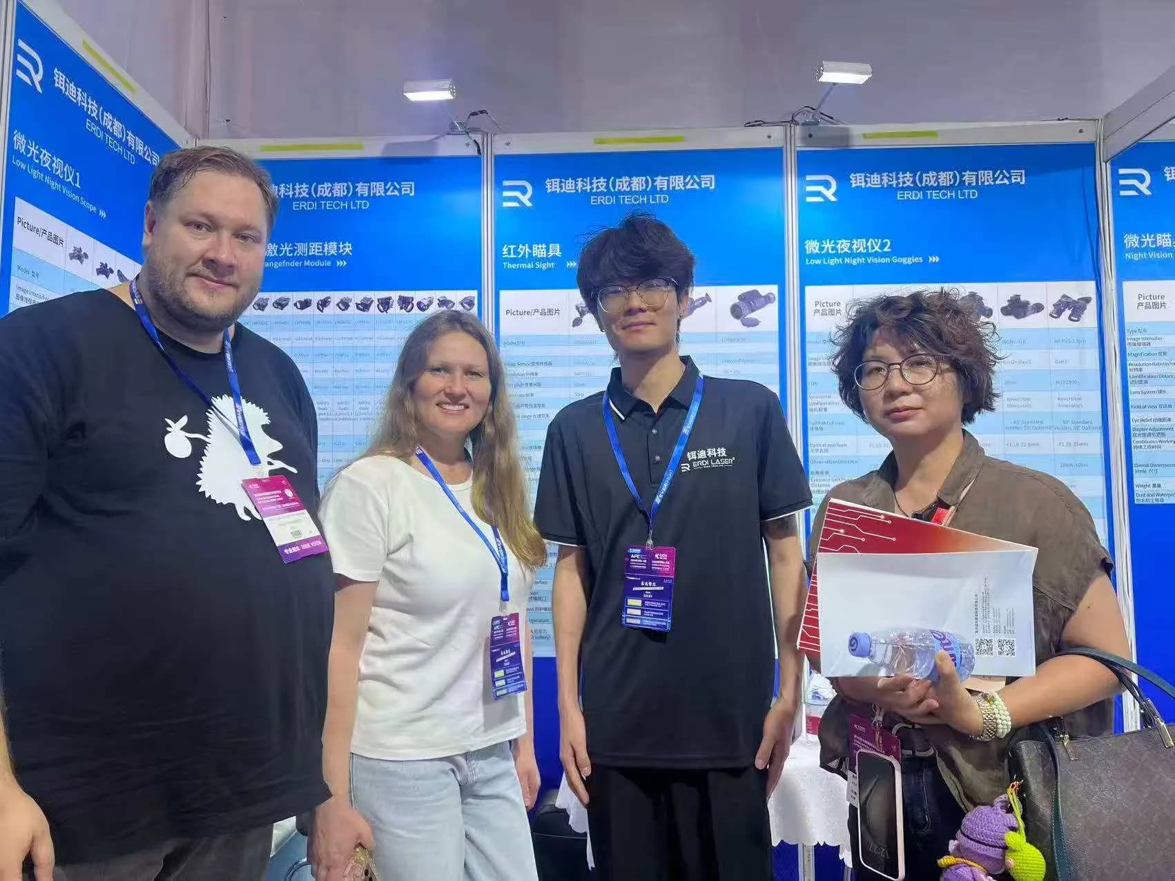
The records below show ERDI optical work and direct product discussions at an optoelectronics exhibition. Product renders remain clearly separated from documentary company media.
ERDI TECH LTD · Chengdu, China
Bring Us the Integration Requirement
Share the target, range, atmosphere, host optics, power, communication, mechanical envelope, environment and acceptance method. The engineering team will organize the open questions before recommending a model.