

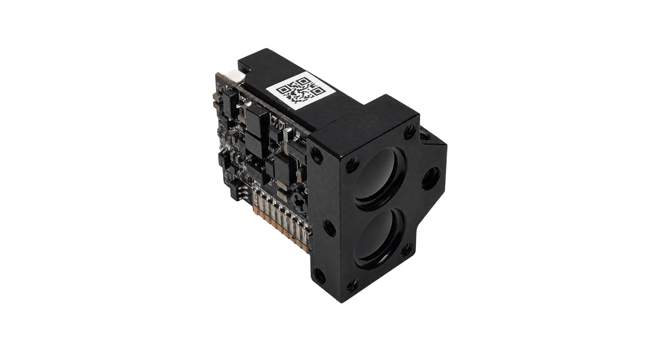
A distance channel can be small without becoming a black box. For designers of handheld observation instruments, compact surveying accessories and civilian UAV payloads, the useful question is not simply how far a laser can reach. It is whether a ranging module can fit the mechanical envelope, operate within the power budget, communicate reliably with the host and deliver a distance whose limitations are understood.
The ERDI SPD1200N3 addresses that integration problem with a 905 nm laser-ranging channel in a package specified at 14.0 × 18.0 × 22.3 mm and no more than 6 g. The supplied user manual gives a 3–1000 m measurement range on a building target, with visibility of at least 10 km and relative humidity no higher than 60%. It specifies a 3.3–5 V supply, a 3.3 V TTL UART interface and a distance-dependent output rate of 2.5–15 Hz. These are useful, concrete starting points for an OEM design—not a promise that every target or weather condition will deliver the maximum range. [1]
This engineering guide explains where those specifications create value, how time-of-flight ranging works and what a host-system designer should validate. Product values come from the September 2026 English user manual, version 1.1. The current ERDI SPD1200N3 product page supplies additional model-specific context. General laser and detector literature is identified separately; it is not presented as a test report for this module.
1. A compact ranging module with an explicit performance envelope
| Parameter | Manual-stated value | How to use it in a design |
|---|---|---|
| Ranging wavelength | 905 ± 5 nm | Use wavelength-compatible windows and optical coatings. |
| Measurement range | 3–1000 m | Building target; visibility ≥10 km; humidity ≤60%. Other targets require validation. |
| Accuracy, distance d ≤100 m | ±0.5 m | Apply within the rated operating range, not below the 3 m minimum. |
| Accuracy, 100 m < d <1000 m | ±(0.5 m + 0.00075d) | d is in metres. The printed formula does not explicitly include exactly 1000 m. |
| Measurement update rate | 2.5–15 Hz | Depends on measurement distance; do not treat 15 Hz as an all-target guarantee. |
| Dimensions / mass | 14.0 × 18.0 × 22.3 mm / ≤6 g | Allow additional room and mass for mounting, harness, window and enclosure. |
| Supply / UART logic | DC 3.3–5 V / 3.3 V TTL | The supply range does not establish 5 V tolerance on communication pins. |
| Power | Standby ≤0.3 W; average ≤0.5 W | These are not specifications for every instantaneous current transient. |
| Startup | ≤200 ms; startup current approximately 200 mA | Separate power-up readiness from time to a valid target measurement. |
| Temperature | Operation −20 to +60 °C; storage −30 to +70 °C | Validate the module's environment inside the assembled instrument. |
| Optical enclosure protection | Lens cavity: IP67 | Not a whole-module or finished-product ingress-protection claim. |
| Laser safety designation | IEC Class 1, as stated in the manual | Confirm the applicable classification documentation and final integration conditions. |
The manual also lists a ranging success rate of at least 98% and a false-alarm rate of no more than 1%. It does not provide the sample size, full statistical definitions or a condition-by-condition dataset. Those figures should therefore remain manual-stated ratings, not become a claim that every field measurement has a 98% probability of success. Likewise, example distances of 1200 m and 1500 m in an N0 example at the end of the document are not SPD1200N3 range specifications. [1]
2. Why the size and mass matter
The module's packaging advantage is easiest to assess through a real system constraint. A small observation instrument may have room for a battery, an imaging channel and a controller but little remaining space for distance measurement. A separate rangefinder adds another housing and operator step. An embedded module allows the designer to bring the distance result into the existing display or data stream, provided the optical and electrical integration is validated.
Using the published outer dimensions, the rectangular bounding volume is:
V_envelope = 14.0 × 18.0 × 22.3 = 5619.6 mm³ ≈ 5.62 cm³.
This is a calculation of the dimensioned bounding box, not a measurement of material volume or the volume of a completed ranging instrument. The enclosure, connector access, strain relief, mounting surfaces and clear optical paths still need space. Nevertheless, a module mass of no more than 6 g and an approximately 5.62 cm³ bounding box make it a practical candidate for space-constrained designs. No “world's smallest” or “world's lightest” ranking is asserted here: such a comparison would require a defined product category and independently maintained market evidence.
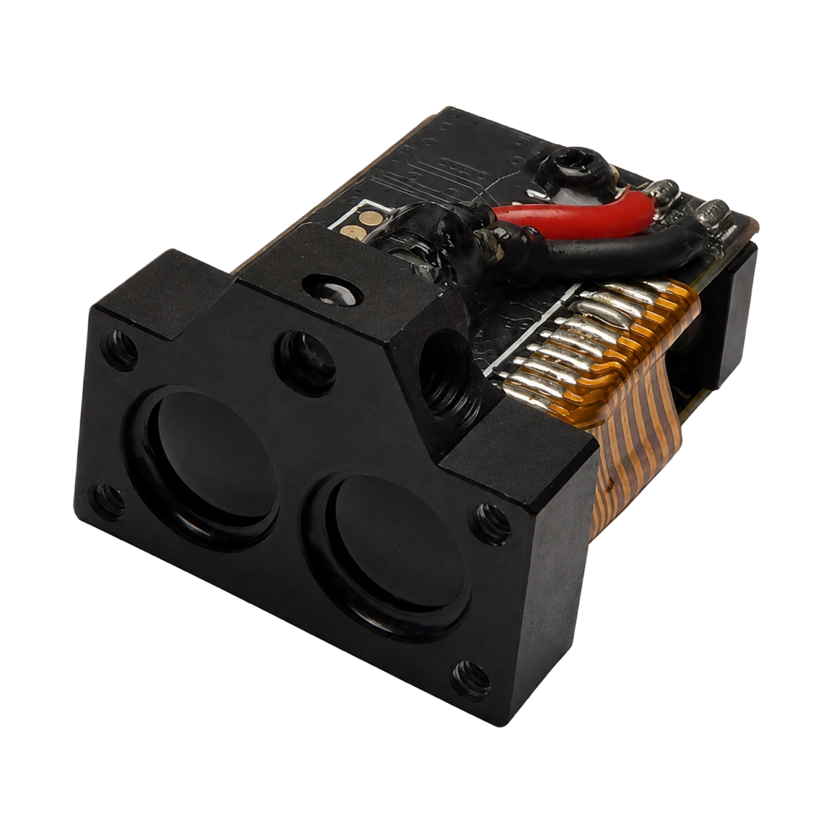
The mechanical drawing and product photograph serve different purposes. The photograph identifies the actual hardware; the drawing defines dimensions and interface orientation. Engineers should use the released drawing and a confirmed CAD revision for fit checks, rather than scale a marketing photograph. ERDI's current product page flags a depth difference between a supplied CAD preview and the released 22.3 mm drawing value. Resolve that revision issue before freezing a cavity or tool, and keep access to both optical apertures. [1, 2]
3. Time of flight: distance from a round-trip interval
Pulsed time-of-flight ranging converts the delay between emission and return into distance, accounting for internal timing offsets. NIST explains the round-trip relationship; its report does not evaluate this module. [3]
R = c × Δt / (2 × n_g)
R is one-way range, c is vacuum light speed, Δt is corrected propagation delay, and n_g is the medium's group refractive index. The factor two represents the return trip. Using c ≈ 3.00 × 10⁸ m/s and n_g ≈1 for an explanatory calculation gives about 6.67 μs at 1000 m—not the module's reporting latency.
| Stage | Physical or processing role | Integration question |
|---|---|---|
| 1 → Emit | A ranging pulse leaves the transmit aperture. | Is the outgoing path clear of the housing and protective window edges? |
| 2 → Propagate and reflect | Part of the illumination reaches the target and returns. | Does the target provide a usable return at the required angle and distance? |
| 3 → Detect and estimate | The receiver and ranging electronics establish a qualified distance. | Have background light, unwanted reflections and invalid results been evaluated? |
| 4 → Report and use | The host receives the result over the serial interface. | Is the value current, correctly decoded and suitable for the application's decision? |
The corresponding sensitivity is δR = c × δt / (2 × n_g): 1 ns represents approximately 0.15 m in air. This calculation does not establish the module's timing resolution or jitter. Displaying one decimal place does not demonstrate sub-decimetre accuracy.
4. Single-photon reception: sensitivity with practical limits
The current ERDI model page identifies SPD1200N3 with a single-photon receiver. The supplied manual provides the operating specifications but does not disclose the detector construction, time-to-digital architecture or estimation algorithm. It is therefore appropriate to explain the technology class, but not to draw an invented internal circuit and label it as this product. [2]
As a general principle, a single-photon avalanche diode, or SPAD, can convert a detected photon into an avalanche event. It must then be quenched and allowed to recover. Technical literature discusses useful sensitivity alongside dead time, dark counts, afterpulsing, optical crosstalk and pile-up effects. Ambient photons can also generate events; high sensitivity does not mean that the receiver automatically distinguishes a target photon from sunlight. These considerations explain why optical filtering, acquisition strategy and statistical processing matter in single-photon time-of-flight systems. The cited model is general detector literature, not a disclosure of ERDI's implementation or evidence of a specific performance improvement. [4]
For the OEM buyer, the relevant benefit is the opportunity to obtain a usable ranging function in a compact module. The acceptance criterion remains performance on the intended scene. Do not convert “single-photon” into a claim of guaranteed range through fog, immunity to ambient light, or a stated number of photons per completed result. None of those product claims is established by the supplied source.
5. Understanding accuracy, output resolution and update rate
Accuracy is a distance-dependent specification
Above 100 m and below 1000 m, the manual combines a fixed term and a distance-proportional term. For example:
| Distance used in the formula | Calculation | Resulting stated accuracy limit |
|---|---|---|
| 100 m | Use the d ≤100 m specification | ±0.5 m |
| 200 m | ±(0.5 + 0.00075 × 200) m | ±0.65 m |
| 500 m | ±(0.5 + 0.00075 × 500) m | ±0.875 m |
| 900 m | ±(0.5 + 0.00075 × 900) m | ±1.175 m |
These values are arithmetic applications of the manual's formula, not new measurements. The extra decimal digits in ±0.875 m do not imply a test instrument of that precision. At exactly 1000 m, the range rating exists but the printed accuracy interval is open at that endpoint; obtain clarification if the boundary is important to the project. For dimensions that require millimetre-level control, this module's published accuracy is not a suitable substitute for a precision displacement sensor.
A data increment is not an uncertainty statement
The manual's protocol guidance expresses distance as d = (256 × H + L) / 10 metres, where H and L are the high and low distance bytes. This encoding has a 0.1 m increment. It does not reduce the ±0.5 m short-range accuracy limit to ±0.1 m. Display resolution, repeatability, systematic error and overall accuracy must be evaluated separately. Since some protocol content is derived from the N0 family, the exact command set and scaling should be confirmed against the delivered SPD1200N3 firmware before a production driver is released. [1, 2]
Output rate is not optical pulse repetition frequency
The specified 2.5–15 Hz describes measurement updates, with the manual noting a dependence on distance. The reciprocal gives a nominal interval of about 400 ms at 2.5 Hz and 66.7 ms at 15 Hz. These are simple rate-to-period conversions, not guaranteed end-to-end latency under all conditions. Single-shot operation may repeat acquisition on a low-reflectivity target before producing a stable result.
A host should therefore timestamp valid readings, set an application-appropriate timeout and avoid silently carrying an old distance forward as though it were new. The document does not specify the internal optical pulse repetition frequency. SPD1200N3 should not be promoted as a kilohertz-output sensor, nor should figures from ERDI's separate high-repetition-rate products be assigned to it. If a project needs much faster distance updates, specify that need independently when comparing modules.
6. Optical design: protect the instrument without obstructing the measurement
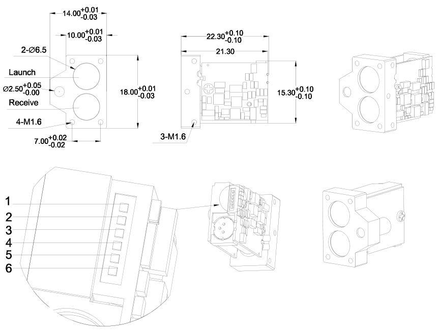
The manual specifies an aspheric lens arrangement and transmit/receive apertures of Ø6.5 mm. It also lists a divergence angle below 6 mrad. The source does not say whether that value is a full-angle or half-angle convention, so a definitive beam-spot diameter should not be calculated from it without clarification. Target size, alignment and the instrument's pointing stability all deserve attention, particularly near the long-distance end of the operating range. [1]
A protective window introduces additional optical surfaces. Its material, coating, wedge, position and clear aperture can affect transmission and unwanted reflections. The document gives integration guidance including H-K9L or fused-silica window materials, a recommended thickness of 2–4 mm, an air gap below 0.5 mm and a wedge-angle tolerance of no more than 3 arcmin. These are source recommendations to review against the actual assembly—not proof that an arbitrary window with those dimensions has been qualified.
The window section mentions an 855–955 nm antireflection band and more than one transmission criterion, without fully resolving the measurement basis. Rather than converting those lines into a guaranteed complete-assembly transmission value, agree a controlled optical drawing and a defined acceptance method with the supplier. Specify whether a transmission number refers to a surface, the whole window, a particular wavelength or a band. The current model page also identifies this section as N0-derived guidance requiring integration review. [1, 2]
In a prototype, check the module with and without the proposed window, on representative targets, and inspect for spurious near returns or loss of detection. Verify that seals and bezels do not clip either optical path. Repeat the check after mechanical assembly and at relevant temperature conditions. These are recommended verification steps; this article does not claim that a particular customer enclosure has already passed them.
7. Electrical integration: a small interface still needs a controlled design
SPD1200N3 uses a DC 3.3–5 V power supply and UART communication at 3.3 V TTL levels. The manual lists 115200 bps as the default baud rate. A 5 V power rail does not make the signal pins 5 V tolerant, and TTL UART should not be connected directly to RS-232 or RS-422 wiring. If the host uses another electrical standard, use an appropriate interface design and confirm voltage limits with ERDI. [1]
| Pin | Name | Manual-stated function / integration note |
|---|---|---|
| 1 | GND | Ground reference. |
| 2 | VCC | DC 3.3–5 V power input. |
| 3 | IO | Reserved; do not assign an undocumented function. |
| 4 | TXD | Module transmit; connect to the compatible host receive input. |
| 5 | RXD | Module receive; connect to the compatible host transmit output. |
| 6 | SW-SHOT | Enable, active high above 1.2 V as described in the manual; confirm behavior for the supplied configuration. |
The startup-current figure of approximately 200 mA deserves particular attention in a battery-powered host. Check rail droop and reset behavior during startup, rather than sizing the rail only from the average power rating. Include the host processor, display, wireless electronics and power-conversion losses when estimating battery endurance; the module's ≤0.5 W average rating alone is not a complete system energy budget.
The protocol guidance describes eight data bits and eight-byte frames with a 55 AA header. It does not explicitly establish every serial framing setting, and some command/status descriptions need firmware-specific confirmation. A robust integration should obtain the controlled protocol revision, check packet length and checksum, handle invalid or absent measurements and recover from interrupted communication. Raw command examples are deliberately not reproduced here as universal, ready-to-run instructions.
ERDI's current product page also describes a laser-indication feature but does not establish its wavelength, optical power, class or validated command set. Do not infer that the 905 nm ranging wavelength describes a visible aiming dot, or that an angle-related field in family-level protocol guidance proves an installed inclination sensor. The N3 should not be promoted as a six-axis IMU, digital compass or ready-made 3D point-to-point measuring system. Confirm the delivered hardware and firmware options explicitly. [2]
8. Application opportunities—and the checks that make them credible
The following are integration opportunities, not named customer deployments or certifications. The manual restricts this product to civilian use and prohibits installation in military equipment. Each use case must also satisfy the applicable equipment safety and local operating requirements. [1]
Handheld outdoor observation instruments
A compact observation device can use a ranging channel to associate a distance with the object being viewed. The low module mass and small mechanical envelope are relevant when the instrument must remain portable. The design still needs a reliable relationship between the viewing direction and ranging direction. Evaluate target selection, distance display, hand movement and the behavior when the beam reaches a background object rather than the intended subject. A distance-only module does not by itself identify the target in an image.
Civilian surveying and site reconnaissance
For preliminary site inspection or recording distances to accessible building surfaces, the published building-target range is directly relevant. A handheld logger can combine a time-stamped range with notes or an externally supplied position. Check the required error budget first: the manual's accuracy is suitable only where that level of uncertainty is acceptable. It is not evidence of survey-grade coordinates, cadastral measurement approval or millimetre construction tolerances. The useful role is a compact distance input, not an unqualified replacement for every survey instrument.
Civilian UAV observation payloads
A payload designer may value the ≤6 g module mass when adding a distance channel to an observation assembly. The complete payload still needs its own mounting, wiring, weather protection and alignment budget. Test on the actual surfaces, slopes, lighting and platform motion expected in service. The distance-dependent 2.5–15 Hz output and the 3 m lower range limit need to be compatible with the intended function. Do not represent the module as a certified flight-altitude sensor, sole collision-avoidance system or safety-critical control solution without the required system validation.
Portable asset and infrastructure inspection
Distance to a wall, structural feature or other diffuse target can add context to a civilian inspection record. UART integration makes it possible for the host to store the measured distance with a timestamp and operator annotation. A returned number is not proof of which object generated it, especially around edges, fences or mixed foreground/background scenes. Define how the operator confirms the target and how the application flags stale or failed measurements. If the environment exceeds the specified temperature range or requires a fully sealed assembly, address that at the instrument level.
Outdoor sports observation and distance aids
Some outdoor distance aids need a light embedded ranging channel rather than a complete standalone instrument. Small targets such as a golf flag present a different problem from a building wall: target size, movement, background objects and pointing stability affect whether a useful return can be acquired. The 1000 m building-target specification must not become a 1000 m flag-detection claim. Demonstrate the intended target and working distances before fixing the product specification. No weapon integration is proposed.
Applications that require another solution or further evidence
Direct measurement of a water surface can fail because the return may not be sufficiently diffuse or may reflect away from the receiver. A “smart water” application label is not evidence of dependable water-level measurement. Dense fog, rain, intense background illumination, dark or inclined targets and partially obstructed optical paths can also change the result. Applications below 3 m, those requiring guaranteed 15 Hz on every target, and those needing millimetre accuracy fall outside what this article can support from the source. Discuss those requirements before selecting a module.
9. Eye safety and environmental ratings belong to the correct level
The manual states IEC Class 1. IEC 60825-1 provides a framework for classifying laser products and includes considerations for components incorporated into a final product. The manual's designation should not be rewritten as an independently verified certificate: no classification report, complete assessment configuration or certificate number was supplied with this article's source. Obtain the appropriate supporting documentation for the delivered configuration and review the completed instrument. [1, 5]
Wavelength alone does not establish eye safety. Neither a 905 nm label nor a Class 1 statement is an invitation to look into the aperture or change laser-drive settings. Follow the manual's handling instructions, which warn against direct viewing and extended continuous laser-on operation. Modifying optics, operating modes or accessible emission conditions may change what needs to be assessed. The separate indication function also needs its own confirmed specifications; do not assign it the ranging channel's designation by assumption.
The same discipline applies to environmental protection. The manual identifies the lens cavity as IP67. Exposed electronics, the connection area and a finished customer's enclosure are not thereby certified IP67. Likewise, −20 to +60 °C is a module operating range, not evidence that the full product will remain within temperature limits in direct sun or near a heat source. Provide the required enclosure, thermal path and verification for the actual instrument.
10. A practical evaluation plan before an OEM design is frozen
A useful evaluation starts with the intended target and decision, not only a maximum-range headline. Record the target material, approximate dimensions, distance, angle and background. Record lighting, visibility, humidity where available, the protective window and the measurement mode. Keep the product and firmware revision with the results so that subsequent changes can be traced.
| Evaluation area | Suggested check | Evidence to keep |
|---|---|---|
| Mechanical fit | Confirm released dimensions, connector access, aperture clearance and mounting alignment. | Drawing/CAD revision and assembled photographs. |
| Power | Observe startup rail behavior and operation across the host's intended supply conditions. | Supply settings and measured voltage/current records. |
| Serial interface | Validate firmware-specific settings, decoding, invalid-result handling and recovery. | Protocol revision and timestamped serial traces. |
| Distance performance | Compare readings with an appropriate reference at representative distances and target angles. | Reference method, individual results, conditions and uncertainty. |
| Update behavior | Measure time to first valid result and valid-update intervals on representative targets. | Distribution of intervals and explicit timeout/failure counts. |
| Optical enclosure | Compare the bare-module result with the proposed window and complete housing. | Window specification and before/after datasets. |
| System safety | Review laser classification evidence and the complete application's risk assessment. | Applicable reports, configuration and operating instructions. |
Keep invalid readings in the record. Report how many attempts were made and how success was defined, rather than calculating performance only from accepted values. Repeatability on a single bright target is not the same as accuracy over the full range. If the application depends on a particular threshold, evaluate the uncertainty and failure behavior around that threshold. These practices turn a promising component into a defensible engineering choice.
11. Choosing SPD1200N3 for the right design
SPD1200N3 is worth evaluating when an OEM project needs a compact 905 nm laser rangefinder module, low mass, modest average power and a UART distance interface, and when its target conditions, accuracy and update behavior match the application. Its value is the combination of these attributes in a small assembly. The case is strongest when integration requirements are specific enough to test, rather than reduced to an unconditional long-range claim.
For a design review, provide the required target type and distance range, acceptable error, minimum valid-update rate, host supply and logic levels, proposed window, operating environment and enclosure constraints. Ask for the current production drawing, hardware/firmware revision, applicable laser-classification evidence and the protocol confirmed for that revision. Commercial terms and delivery arrangements should be confirmed separately; this article does not establish price, stock, lead time or minimum order quantity.
Explore the SPD1200N3 product specifications and controlled resources, download the English user manual, or contact ERDI for a product-specific technical review. More laser-ranging products and technical resources are available at erdicn.com.
Sources and scope of evidence
- ERDI, SPD1200N3 User Manual, English, version 1.1, September 2026. Pages 1–3: ratings and modes; pages 4–5: mechanical and optical integration guidance; pages 6–7: protocol and handling; page 8: target/environment notes and N0 examples. The N0 example distances are not used as N3 specifications.
- ERDI, SPD1200N3 official product page, checked 6 October 2026. Model-specific clarification of single-photon reception, indication boundaries, firmware-dependent guidance and drawing/CAD revision differences.
- Stone, W. C., Juberts, M., Dagalakis, N., Stone, J. Jr., and Gorman, J. J. Performance Analysis of Next-Generation LADAR for Manufacturing, Construction, and Mobility. NISTIR 7117, 2004. DOI: 10.6028/NIST.IR.7117. General time-of-flight measurement principles; not a product test or endorsement.
- Incoronato, A., Locatelli, M., and Zappa, F. Statistical Modelling of SPADs for Time-of-Flight LiDAR. Sensors 21(13), 4481, 2021. DOI: 10.3390/s21134481. General detector behavior and nonidealities; not the module's disclosed internal design.
- IEC 60825-1:2014, Safety of laser products—Part 1: Equipment classification and requirements. General classification framework; its citation does not establish certification of the SPD1200N3 or a customer's finished instrument.
Engineering note: numerical examples are explicitly identified calculations. Proposed application and validation steps are engineering guidance, not completed field trials. For procurement and integration, use the controlled documentation for the actual delivered configuration.