

Compact Ranging with Laser Indication
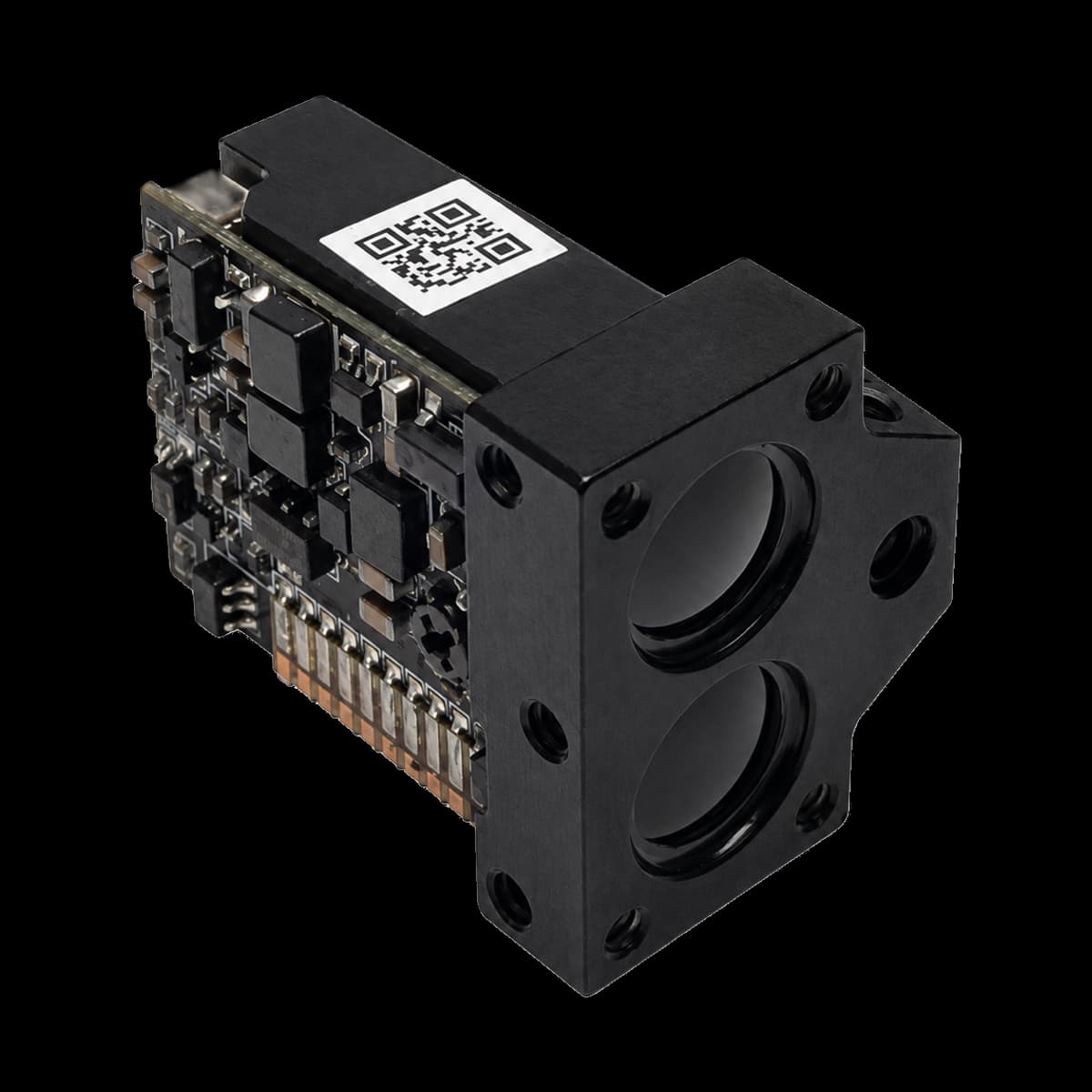
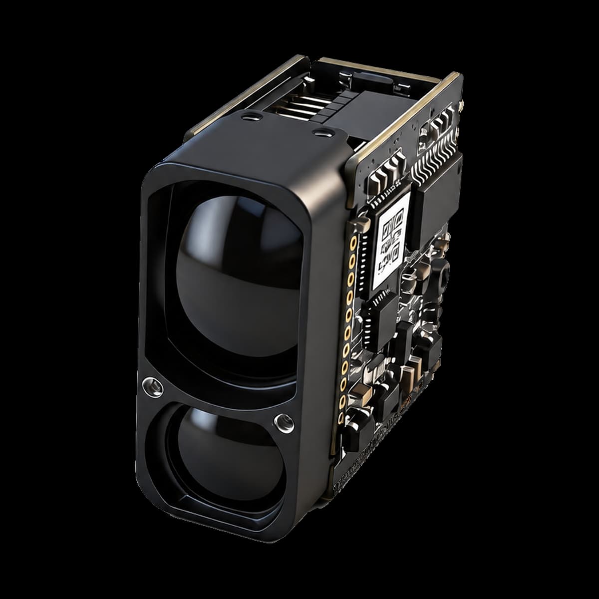
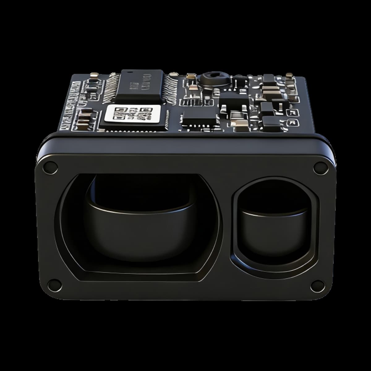
SPD1200N3 combines a 905 nm ranging laser and single-photon receiver with a laser-indication function. ERDI confirms that its ranging laser and receiver are shared with SPD1200ZG; the model-specific ranging limits, mechanical design and indication functions must still be evaluated separately.
SPD1200ZG provides inertial orientation information. SPD1200N3 provides laser indication instead; this is not a claim of a six-axis IMU, compass heading or 3D point-to-point measurement for N3.
The N3 specification states a 3–1000 m range on a building target under visibility of at least 10 km and humidity no greater than 60%. The nominal rectangular body is 14 × 18 × 22.3 mm and weighs no more than 6 g.
Detailed SPD1200N3 Specifications
Read the values together with their source conditions. Literature and related-model data do not replace these ratings.
| Parameter | Value | Source condition |
|---|---|---|
| Laser wavelength | 905 ± 5 nm | Ranging emitter; not the indication-laser wavelength |
| Beam divergence | <6 mrad | See the controlled model document |
| Optical element | Aspheric lens | See the controlled model document |
| Receive / transmit aperture | Ø6.5 mm | See the controlled model document |
| Measurement range | 3–1000 m | Building target; visibility ≥10 km; humidity ≤60% |
| Ranging accuracy | ±0.5 m at d ≤100 m; ±(0.5 m + 0.00075d) for 100 m < d <1000 m | d is distance in meters; no additional endpoint accuracy inferred |
| Measurement update rate | 2.5–15 Hz | Varies with distance; not the laser pulse repetition rate |
| Measurement success rate | ≥98% | Source rating; validate representative targets and conditions |
| False alarm rate | ≤1% | Source rating; not a universal field guarantee |
| Communication interface | UART, 3.3 V TTL; customizable | See the controlled model document |
| Default baud rate | 115200 bps | See the controlled model document |
| Supply voltage | DC 3.3–5 V | Does not imply 5 V tolerance on serial inputs |
| Startup time | ≤200 ms | See the controlled model document |
| Instantaneous startup current | Approximately 200 mA | See the controlled model document |
| Standby power consumption | ≤0.3 W | See the controlled model document |
| Average power consumption | ≤0.5 W | See the controlled model document |
| Operating temperature | −20 to +60 °C | See the controlled model document |
| Storage temperature | −30 to +70 °C | See the controlled model document |
| Ingress protection | IP67 within the lens cavity only | Not a whole-module or finished-equipment rating |
| Laser safety class | IEC Class 1 stated in the ranging specification | Do not extend this rating to indication/alignment modes or the finished system without confirmation |
| Nominal body dimensions / material | 14 × 18 × 22.3 mm; rectangular; 6061 aluminum alloy | Use the controlled mechanical drawing and tolerances |
| Weight | ≤6 g | See the controlled model document |
Functional Description
Single measurement initiates one target-distance measurement and returns the result over the serial interface; the source describes repeated acquisition for low-reflectivity targets until a stable reading is obtained.
Continuous measurement repeatedly reports target distance at a distance-dependent 2.5–15 Hz update rate.
The serial baud rate can be configured to match host requirements. Use firmware-matched packet definitions and test command, response, checksum and failure handling on the ordered configuration.
Electrical Interface Definition
| Pin | Signal | Function |
|---|---|---|
| 1 | GND | Power-supply ground |
| 2 | VCC | Positive supply input |
| 3 | IO (reserved) | Reserved for expansion |
| 4 | TXD | Signal output: module to host |
| 5 | RXD | Signal input: host to module |
| 6 | SW-SHOT | Function enable, active high (>1.2 V); confirm supplied configuration before wiring |
Check the numbered connector view before wiring. Supply voltage and UART input tolerance are different electrical limits.
Mechanical Dimension Drawing and Electrical Interface Diagram
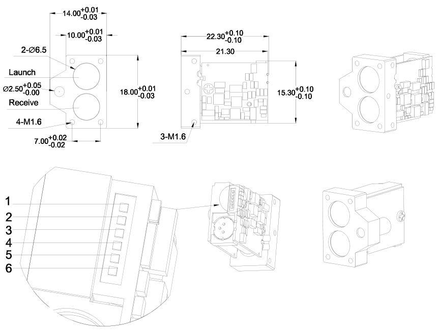
The model PDF controls product claims. Independent literature explains general principles and does not qualify this module.
Pulsed Laser and Single-Photon Receiver Technology
The N3 laser and single-photon receiver pairing is confirmed by ERDI. The following literature explains general device physics; it does not disclose the internal part numbers, circuit or firmware and is not N3 test data.
Transmit pulse and timing reference
Target reflection and receive optics
Photon detection and event timing
Return estimation and host output
Pulsed Emission and the Timing Reference
Direct time-of-flight ranging measures the delay between a transmitted optical pulse and its return. In the usual propagation approximation, R = cΔt / 2: R is the one-way range, Δt is the round-trip travel time, and c is the propagation speed. Division by two accounts for the outward and return paths. Pulse shape, timing uncertainty, receiver response and target geometry influence the result. [R1]
Avalanche Detection and Recovery
A SPAD operates above avalanche breakdown so that an absorbed photon can initiate a detectable avalanche. Quenching stops that avalanche, followed by recovery. Single-photon sensitivity does not mean every incident photon is detected. Dark counts, afterpulsing and, in detector arrays, neighbor-induced optical crosstalk can also contribute events. [R2]
From Event Timing to a Histogram
Published direct-ToF designs encode arrival time with a time-to-digital converter and accumulate events in histogram bins. A concentration of events can indicate a return delay. Hutchings and colleagues demonstrate this in a research imager; the example does not identify ERDI's internal circuit or algorithm. [R3]
Separating Signal from Ambient Background
Detections do not arrive with labels identifying their origin. Under the statistical model studied by Rapp and Goyal, pulse-related returns cluster in time while steady background contributes broadly distributed events. Separating a return from ambient light is therefore a statistical task, not simply counting every photon as useful signal. [R4]
Dead Time and Pile Up
During recovery, a detector cannot register another photon. In first-event acquisition, early detections can prevent later arrivals from being recorded. At high flux this selection can distort the distribution, a phenomenon called pile-up. More incident light is not automatically better. The effect depends on the acquisition architecture and operating conditions. [R5]
Detector Crosstalk and Window Reflections
Detector-array crosstalk occurs when an avalanche in one detector causes an unwanted event in another. Optical assembly crosstalk is different: emitted light can reflect inside a protective window and reach the receiver without the intended target round trip. ST documents resulting false or shortened readings in its own sensor. Its distances, calibration procedures and immunity claims must not be transferred to ERDI modules. [R2] [R6]
Evaluate the Complete Installation
Target and range
Match target size, reflectivity, angle and background light to the model's source-stated measurement conditions.
Power and interface
Verify startup current, signal voltage, common ground, connector orientation and firmware-matched serial packets.
Mechanical envelope
Release mounting and optical apertures against the controlled drawing and tolerances, not a rendered image alone.
Qualification and safety
Test the assembled window and enclosure. Reassess accessible emission, operating modes and labeling in the finished equipment.
Civilian Integration Applications
- Civilian optical observation and telescopic instruments
- Thermal-imaging and night-vision accessories
- Industrial measurement, railway and infrastructure inspection
- Smart water management and outdoor field measurement
Application examples are evaluation contexts, not proof of fitness without system testing.
Configuration, Window and Safety Review
The laser-indication function is confirmed, but its wavelength, power, safety classification and control commands are not specified in the supplied N3 source. Obtain these configuration details before integration; do not repurpose the ranging wavelength or an unrelated LD command as the indication specification.
The English manual includes Optical Window Selection, Communication Protocol and Safety Warnings and Precautions adapted from N0 at ERDI's request. These additions are integration guidance, not proof that every N0 firmware command is implemented by N3. Angle commands apply only to angle-equipped configurations; no angle capability is promised for N3.
The supplied CAD preview spans 18 × 14 × 21.3 mm, while the nominal source body depth is 22.3 mm. Use the dimensioned drawing and request engineering confirmation before enclosure release. The preview has not been stretched to conceal the difference.
Do not look into the laser aperture or direct an indication/alignment beam toward anyone's eyes. The finished equipment, optics and operating modes require a separate laser-safety assessment. The lens-cavity IP67 statement does not protect the exposed electronics.
Use a 905 nm-compatible protective window and assess transmit-to-receive reflections, contamination, alignment, temperature and ambient light in the assembled instrument. Confirm the N0-derived window dimensions and coatings for the N3 installation.
Frequently Asked Questions
How does SPD1200N3 differ from SPD1200ZG?
ERDI confirms a shared ranging laser and single-photon receiver. N3 adds laser indication, whereas ZG provides inertial orientation information. Their source-stated ranges, mechanical dimensions, firmware functions and safety conditions are not interchangeable.
Does N3 measure 1200 m because of its model name?
No. The supplied N3 specification states 3–1000 m with a building target, visibility ≥10 km and humidity ≤60%. The product name does not override this rating.
What wavelength and power does the indication laser use?
These values and the indication-mode safety class are not established by the supplied source. The 905 ± 5 nm value is the ranging wavelength. Request configuration-specific indication data and commands from ERDI.
Can I use every N0 protocol command on N3?
Do not assume compatibility. The English N3 manual incorporates the N0 protocol as requested guidance; verify the ordered N3 firmware. An angle command is conditional on angle-sensor hardware, and the LD continuous-on command is not evidence of the N3 indication control protocol.
Can I design the enclosure directly from the 3D preview?
No. The supplied CAD preview and dimensioned drawing have a 1 mm depth discrepancy. Use the drawing with tolerances and obtain an approved CAD revision before design release. The original STEP file is available through an engineering request.
What lead time applies to my quantity?
In stock. Dispatch is within 7 working days for 1–30 pcs, 30 working days for 31–100 pcs, and 45 working days for 101 pcs or more, counted from payment confirmation. Shipping is included to the shipping address you enter.
Does single-photon reception mean one photon always gives a valid distance?
No. A detection may originate from the target, background light or detector noise. A reliable estimate needs sufficient evidence to distinguish the return. Photon-efficient research does not establish a universal one-photon measurement guarantee. [R4]
What is the role of a TDC and a histogram?
A TDC digitizes arrival time; a histogram counts events in time intervals. They can reveal repeated return timing. This explains a general approach, not this module's internal architecture. [R3]
Can strong sunlight affect a single-photon receiver?
Yes. Strong background illumination can increase unrelated detections and distort acquisition at high photon flux. Single-photon sensitivity is not sunlight immunity. Evaluate the complete installation under representative lighting. [R5]
Does a finer time bin equal better specified ranging accuracy?
No. Final accuracy includes more than digitization, and an estimator can use neighboring-bin information. Compare model-specific accuracy and test conditions, not an isolated timing number. [R3]
Are detector dead time and measurement update rate the same?
No. Dead time is an interval of detector or timing-circuit unavailability. Product update rate describes how often completed measurements are reported. Do not infer one from the other without the acquisition specification. [R2]
Why should the final protective window be tested?
Internal reflections can send transmitter light toward the receiver and create unwanted near-range signals. Check the assembled window rather than assuming a bare-module result will remain unchanged. Use an ERDI-approved procedure for the ordered configuration, not another manufacturer's calibration recipe. [R6]
Is the quoted maximum range guaranteed for every target?
No. Target reflectivity, incidence angle, beam footprint and background illumination affect practical ranging. Compare the intended target and installation with the conditions accompanying the model's stated range. [R1]
Does this technical explanation establish the same architecture for every N-series model?
No. Generic literature is not a model-specific bill of materials. Do not infer the internal receiver, timing circuit, histogram processing, indication function or firmware compatibility of SPD1200N0, SPD1200N2 or SPD1200N4 from a related model. Use the current specification and obtain configuration-specific confirmation where needed.
References and Evidence Boundaries
- [R1] Performance Analysis of Next-Generation LADAR for Manufacturing, Construction, and Mobility
Stone et al., NISTIR 7117 (2004), DOI 10.6028/NIST.IR.7117. Sections 2.1–2.1.1 support round-trip ranging and practical influences, not an ERDI receiver design or rating.
- [R2] Statistical Modelling of SPADs for Time-of-Flight LiDAR
Incoronato, Locatelli and Zappa, Sensors 21(13), 4481 (2021). Sections 2–3 cover avalanche operation, recovery, afterpulsing, array crosstalk and acquisition limitations. They do not identify ERDI's implementation.
- [R3] A Reconfigurable 3-D-Stacked SPAD Imager With In-Pixel Histogramming for Flash LIDAR or High-Speed Time-of-Flight Imaging
Hutchings et al., IEEE JSSC 54(11), 2947–2956 (2019), DOI 10.1109/JSSC.2019.2939083. Sections II–III demonstrate timing, histogramming and range estimation. The research imager's architecture and performance are not ERDI specifications.
- [R4] A Few Photons Among Many: Unmixing Signal and Noise for Photon-Efficient Active Imaging
Rapp and Goyal, IEEE TCI 3(3), 445–459 (2017), DOI 10.1109/TCI.2017.2706028. Sections II–III explain statistical signal/background separation. Neither the algorithm nor experimental results are claimed for ERDI.
- [R5] Photon-Flooded Single-Photon 3D Cameras
Gupta, Ingle, Velten and Gupta, author manuscript v2 (2019), repository DOI 10.48550/arXiv.1903.08347. Sections 1–3 explain first-event pile-up and high-flux tradeoffs. First-event acquisition is architecture-specific; the prototype is not an ERDI test.
- [R6] A guide for using the VL53L8CX, low-power, high-performance Time-of-Flight multizone ranging sensor
STMicroelectronics UM3109, Rev 12 (August 2025), Calibration flow. Manufacturer evidence of protective-window reflections and unwanted range signals in another manufacturer's 940 nm system. Its calibration instructions, dimensions and immunity claims do not apply to ERDI modules.
Independent literature supports the explanations, not module qualification. Use the source-linked model manual and ERDI configuration confirmation for procurement and design release.