

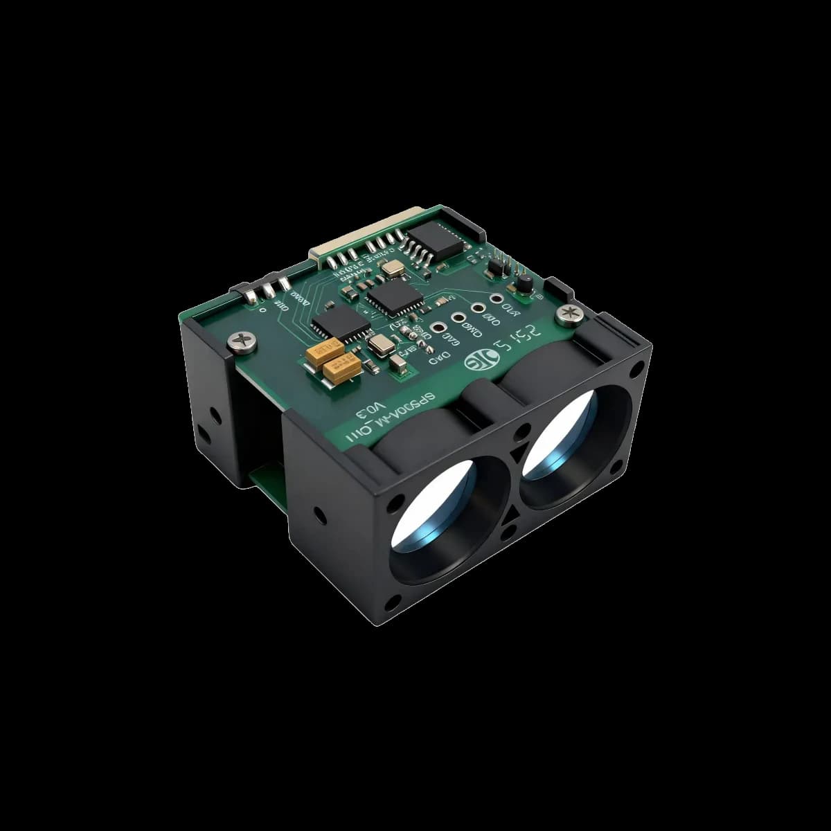
Engineering conclusion. A 905 nm high-rate direct time-of-flight module is valuable when the host needs more than an occasional distance value. Its real advantage is a shorter observation interval, faster motion tracking, denser spatial sampling, and more opportunities to reject outliers or fuse range with control data. Those benefits are achieved only when optical return, receiver bandwidth, serial throughput, processing latency, target reflectivity, ambient light, mounting, and laser safety are treated as one system. ERDI's controlled 905 nm portfolio covers compact 100-200 Hz sensors and industrial modules with 1 kHz default or 1 kHz/50 Hz adaptive output, spanning controlled datasheet ranges from 20 m to 1500 m. Range, rate, and accuracy are conditional values, not interchangeable slogans.
This guide is written for OEM engineers, system integrators, automation teams, UAV payload designers, machine builders, infrastructure-monitoring specialists, and technical buyers evaluating a 905 nm high repetition rate laser rangefinder module, high-frequency DToF LiDAR module, 1 kHz laser distance sensor, or industrial LiDAR distance sensor. It explains the physics, quantifies the useful trade-offs, compares verified product families, and provides an integration and acceptance framework suitable for global B2B projects.
1. What high repetition rate means in a real ranging product
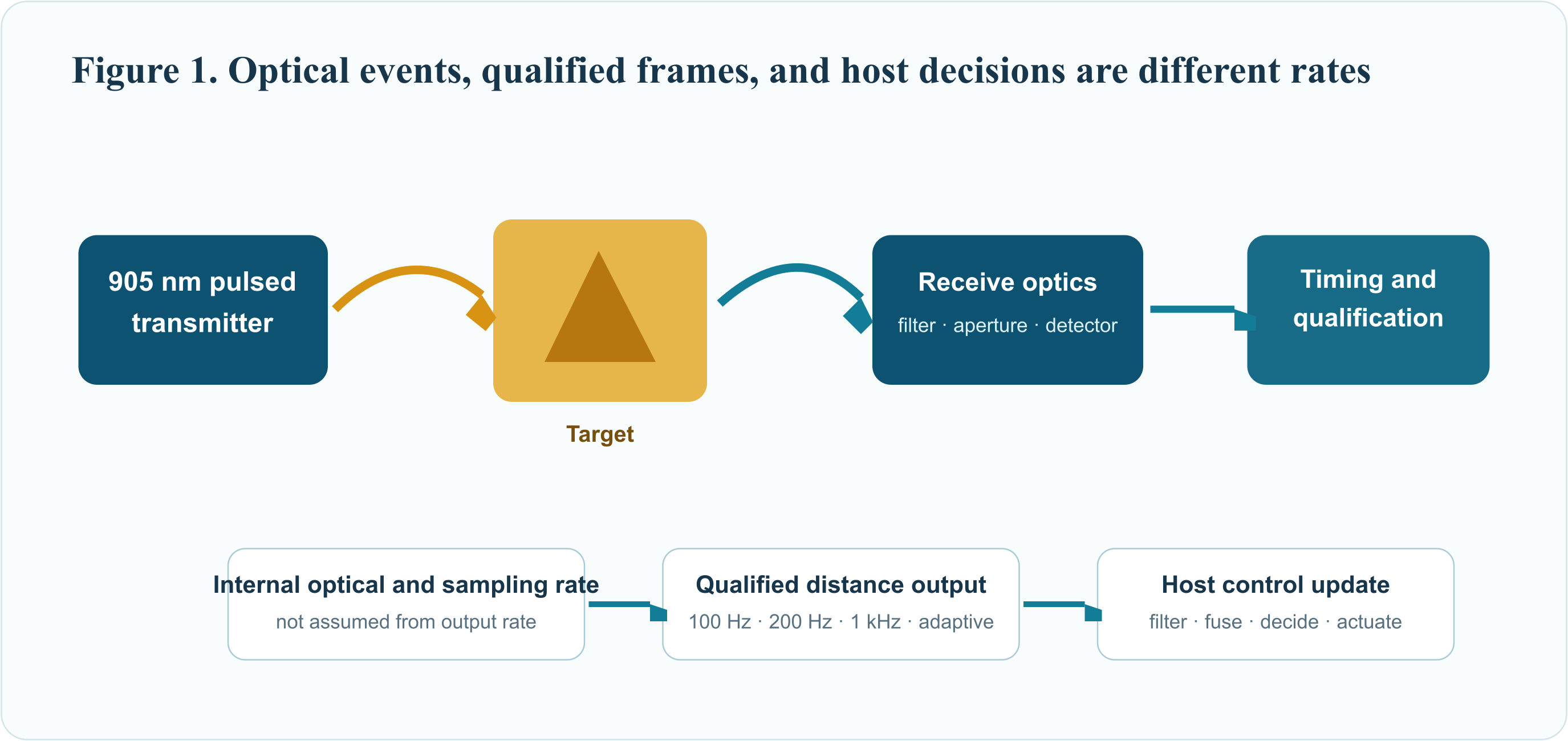
Three rates are often mixed together in marketing: the optical pulse repetition frequency of the transmitter, the internal sampling or accumulation rate of the receiver, and the rate at which a qualified distance frame is delivered to the host. They can be different by orders of magnitude. A module may fire or process multiple optical events to generate one output frame; it may also reduce its output rate when the return becomes weak so that more evidence can be accumulated. Therefore this article uses measuring frequency or output update rate when quoting ERDI datasheets. It does not assign an internal laser pulse repetition frequency that is not published in the controlled source.
At 1 kHz, a new distance frame is nominally available every 1 ms. At 200 Hz, the interval is 5 ms; at 100 Hz, 10 ms; and at 50 Hz, 20 ms. These are ideal frame intervals before host-side buffering, link transport, filtering, scheduling, and actuator latency. The correct engineering question is not merely “How many hertz?” It is “How old is the most recent valid distance when the controller acts, and how reliably is that value produced in the target scene?”
Tframe = 1 / foutAt 1 kHz, Tframe = 1 ms. End-to-end control latency also includes acquisition, qualification, transport, host processing, and actuation.
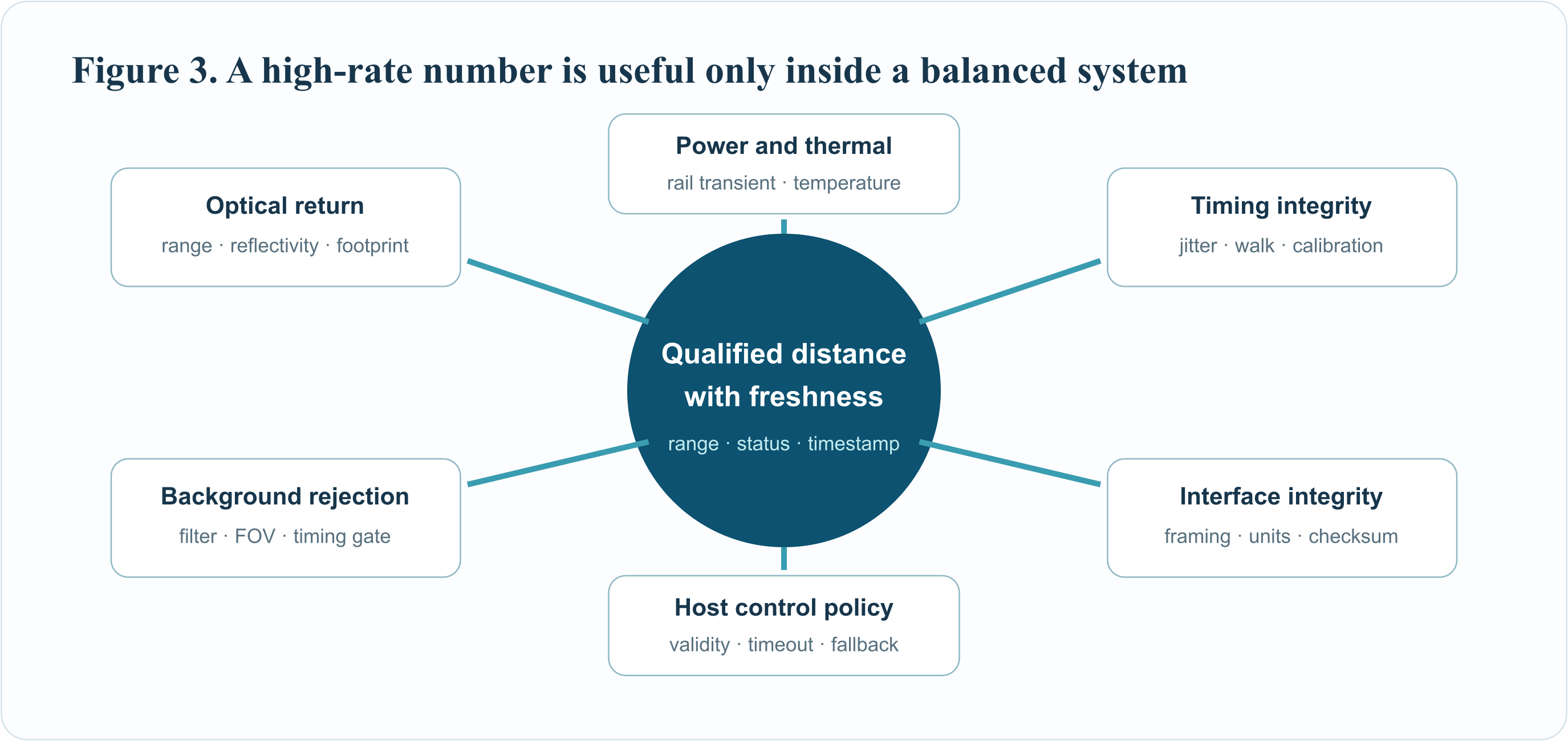
High output rate is most useful for moving targets, scanning mechanisms, vibration measurement, closed-loop positioning, fast safety monitoring, and navigation. It can also improve confidence because more independent observations are available in a fixed time window. But averaging more samples increases delay, and weak returns may force a slower operating mode. A responsible design therefore specifies both the nominal rate and the validity policy: how invalid, saturated, low-confidence, out-of-range, or stale frames are handled.
2. Direct ToF equations and the timing budget
A pulsed DToF rangefinder records the round-trip delay between a transmit reference and the received optical return. In vacuum, the speed of light is exactly 299,792,458 m/s under the SI definition. In air the propagation velocity is slightly lower and depends on refractive index; for many industrial ranges the simple vacuum approximation is adequate, while precision metrology may require atmospheric correction.
R = c(Δt - tsys) / 2R is one-way distance, Δt is the measured round-trip interval, and tsys is the calibrated electrical and optical system delay.
The factor of two is required because light travels to the target and back. One nanosecond of round-trip timing corresponds to approximately 0.1499 m of one-way range. A 1 cm range increment corresponds to about 66.7 ps of round-trip time. This conversion is useful for an error budget: timing-reference jitter, detector jitter, threshold walk, quantization, temperature drift, calibration residuals, and photon statistics all contribute to the final distance uncertainty. Resolution, repeatability, and accuracy are not synonyms. Resolution is the output increment; repeatability describes dispersion under repeated conditions; accuracy includes systematic offset from the reference distance.
σR ≈ (c/2) √(σtx2 + σrx2 + σTDC2 + σclk2 + σfit2)A conceptual root-sum-square timing model. Correlated and systematic terms must be calibrated separately rather than hidden inside random noise.
The link budget explains why a module can deliver its maximum range on a large 90% reflector but a much shorter range on a 10% target. In a simplified diffuse-target model, received energy decreases strongly with distance and is affected by transmitter energy, target reflectivity, projected target area, atmospheric transmission, receiver aperture, optical transmission, detector efficiency, and overlap between transmit and receive fields. Real targets are not ideal Lambertian surfaces: retroreflective tape, glass, wet coatings, polished metal, mesh, dark textiles, and oblique surfaces can behave very differently.
Ns ∝ Etx · ρ · Arx · ηopt · ηdet · Tatm2 / R2A proportional photon or signal-count relationship for comparison, not a product guarantee. Geometry, beam divergence, target extent, and receiver architecture change the exact lidar equation.
3. Why 905 nm is an effective OEM wavelength
905 nm occupies a mature near-infrared ecosystem. Silicon photodetectors retain useful sensitivity at this wavelength, pulsed semiconductor emitters and optical coatings are widely available, and compact transmit-receive assemblies can be designed for industrial cost, size, and power targets. The wavelength is invisible to the human eye, so visible brightness cannot be used as a safety indicator or alignment method.
The main advantage is system practicality, not a universal claim that 905 nm is superior in every environment. Solar background, water absorption, atmospheric transmission, detector responsivity, optical filter bandwidth, required range, permitted aperture, eye-safety classification, thermal design, and bill of materials all interact. A narrowband interference filter centered on the real emission spectrum can suppress out-of-band ambient light, but angle of incidence and temperature can shift the filter passband. The filter, window, lens, and emitter spectrum must be evaluated together.
ERDI datasheets for the 905 nm family state Class 1 photobiological safety for the ranging source. That statement belongs to each controlled module and its stated configuration. IEC 60825-1 classifies laser products and requires assessment of accessible emission under defined operation, maintenance, service, and fault conditions. An OEM that changes optics, drive conditions, enclosure, scanning behavior, duty cycle, or access conditions must evaluate the final laser product. A component claim is not a blanket certificate for every host system.
4. Engineering advantages of a high update rate
4.1 Lower sampling latency for dynamic control
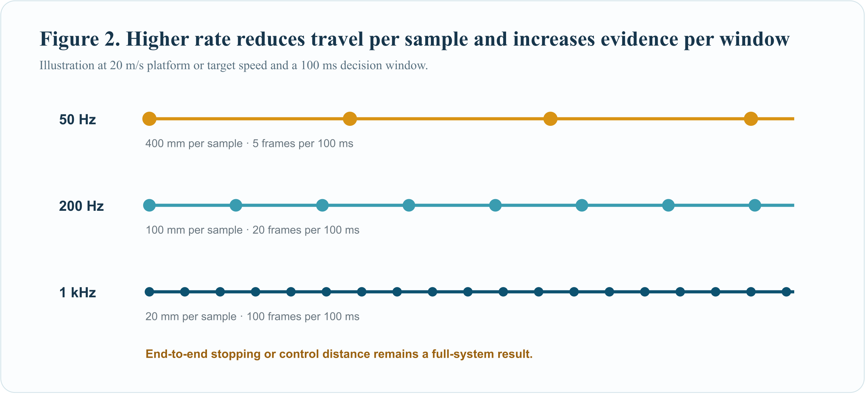
A 1 kHz stream gives the controller a nominal 1 ms sampling interval. At a closing speed of 20 m/s, the target moves 20 mm during that interval; at 50 Hz, it moves 0.4 m. This does not mean the 1 kHz system will stop a machine within 20 mm. Braking distance also includes filtering, communication, controller execution, network scheduling, actuator response, mechanics, and the uncertainty of the measurement. It does show why the rate matters when the distance is changing quickly.
Δx = v / foutDistance travelled between nominal samples. At v = 20 m/s: 20 mm at 1 kHz, 100 mm at 200 Hz, and 400 mm at 50 Hz.
4.2 Denser spatial sampling on a moving platform
When a single-point rangefinder is mounted on a moving vehicle, rotating mirror, gimbal, linear stage, or UAV, time samples become spatial samples. With platform speed v, the along-track sample pitch is approximately v/fout. Higher rate can reveal narrow features that a slower stream skips. The full system must still account for beam footprint, pointing uncertainty, attitude data, synchronization, and target motion; a dense numerical sequence is not automatically a dense independent measurement if successive footprints overlap.
4.3 More observations for robust filtering
Within a fixed 100 ms decision window, 1 kHz nominally provides 100 frames, 200 Hz provides 20, and 50 Hz provides five. The host can use a median, trimmed estimator, innovation gate, or motion model to reject isolated outliers. If independent zero-mean noise dominates, averaging N samples can reduce standard error approximately with the square root of N. The assumption fails when noise is correlated or when target distance changes during the window.
σmean = σ / √NValid for independent, identically distributed samples. Averaging does not remove systematic bias, multipath, saturation, misalignment, or a moving-target trend.
4.4 Better temporal alignment with cameras and inertial sensors
High-rate distance data can be associated more closely with camera frames, encoder positions, IMU measurements, or robot-control cycles. The value depends on timestamps. A host that timestamps only after a serial frame arrives measures communication completion, not the optical event time. For tight fusion, establish whether the module exposes a trigger, synchronization input, deterministic delay, or only an asynchronous stream; then characterize latency and jitter experimentally.
4.5 Adaptive rate extends usable operation
Several ERDI long-range modules specify 1 kHz or 50 Hz, switched automatically to match reflected-signal intensity. This is an important engineering feature, but it changes the system contract. Strong returns support fast updates; weak returns may be delivered more slowly so the receiver can accumulate or qualify sufficient evidence. Control software should monitor inter-frame time and freshness rather than assume a fixed 1 ms cadence at all ranges and reflectivities.
5. The trade-offs that determine usable performance
5.1 Unambiguous range and pulse association
For a simple periodic pulse train without coding or disambiguation, a return should arrive before the next indistinguishable transmit event. The approximate ambiguity-free range is c/(2frep). This formula applies to the optical pulse repetition frequency, not automatically to the output-frame rate. Multi-rate operation, pulse coding, range gates, or other association logic can extend or manage ambiguity, but the implementation must be verified rather than assumed.
Runamb ≈ c / (2 frep)A first-order periodic-pulse limit. Coding and disambiguation can change the practical limit; fout must not be substituted for frep without architecture evidence.
5.2 Signal-to-background ratio
Ambient light generates receiver events that are not synchronized with the transmitted pulse. A narrow optical bandwidth, controlled receiver field of view, short timing gate, baffling, and statistical qualification improve the signal-to-background ratio. “100 kLux ambient-light immunity” is meaningful only with the accompanying target, distance, orientation, spectrum, optical setup, and temperature. Lux is weighted for human vision and does not fully describe near-infrared spectral irradiance at 905 nm.
5.3 Beam footprint and target size
Beam divergence converts distance into footprint. For a small divergence angle θ in radians, spot diameter grows approximately as d0 + Rθ. A 4 mrad beam expands by about 4 mm per metre, excluding the initial aperture. If only part of the beam strikes the desired object, nearby background can dominate. Compact models with degree-scale fields of view create much larger footprints and should be matched to short-range obstacle, focusing, or presence-detection tasks.
d(R) ≈ d0 + RθSmall-angle footprint estimate. Use the model-specific beam or FOV definition; transmitter divergence and receiver FOV are not always the same quantity.
5.4 Serial throughput and buffering
At 1 kHz, a compact four-byte payload is only 4 kB/s before UART framing, which is readily transported at a 460,800 baud default interface. The system still needs robust framing, checksum verification, timeout handling, endianness, unit conversion, and reconnect behavior. For example, several controlled H-series datasheets describe a little-endian distance payload in centimetres. The compact VB series reports millimetres. Mixing those units or treating an out-of-range sentinel as a valid distance can create a dangerous control fault.
5.5 Thermal and power integrity
High-rate operation stresses the transmitter, receiver, power rail, and processor differently from a low-rate laboratory test. Validate supply transients at the module connector, not only at the power source. Measure enclosure temperature, warm-up drift, airflow, and behavior at the specified temperature limits. Some module manuals explicitly warn that reverse-polarity and overvoltage protection are not provided; the host should implement appropriate protection when required.
6. Verified ERDI 905 nm module families
The following table summarizes controlled public datasheets available through ERDI's official website. Values remain subject to the conditions and notes in each model's current datasheet. No price, stock, certification, or final-system suitability is inferred here.
| Product and official page | Controlled range condition | Published measuring frequency | Resolution and interfaces | Integration profile |
|---|---|---|---|---|
| 20 m compact DToF sensor | 0.05-20 m at 90% reflectivity; 0.05-10 m at 10%; 8 m at 60 kLux on a 90% reflector | 200 Hz; selectable 100/50/20/10/1 Hz | 1 mm; UART/I2C; 3-3.6 VDC | 21 × 15 × 7.43 mm, 1.5 g; drones, robots, AGVs, light curtains, focusing |
| 50 m compact DToF sensor | 0.05-50 m at 90%; 0.05-20 m at 10%; 10 m at 60 kLux on a 90% reflector | 100 Hz in the formal specification table | 1 mm; UART/I2C; 3.3-5 VDC | 18.7 × 11.8 × 13.3 mm, 1.3 g; compact high-speed monitoring and robotics |
| 50 m high-speed industrial module | 0.05-50 m at 90%; 0.05-15 m at 10%; 45 m at 100 kLux on a 90% reflector | 20 Hz-10 kHz; 1 kHz default | 1 cm; UART; 9-36 VDC | 38 × 20 × 30 mm, 15 ±2 g; overhead crane and carriage positioning |
| 100 m industrial DToF module | 0.05-100 m at 90%; 0.05-30 m at 10%; 100 kLux stated in the specification | 20 Hz-10 kHz; 1 kHz default | 1 cm; UART/I2C; 9-36 VDC | 33 × 34 × 18 mm, 20 ±2 g; level, displacement, wind-power and slope monitoring |
| 200 m industrial DToF module | 0.05-200 m at 90%; 0.05-70 m at 10%; 100 kLux stated | 20 Hz-10 kHz; 1 kHz default | 1 cm; UART/I2C; 9-36 VDC | 33 × 34 × 18 mm, 20 ±2 g; port cranes, conveyors, tunnel monitoring |
| 300 m industrial DToF module | 0.05-300 m at 90%; 0.05-100 m at 10%; 100 kLux stated | 1 kHz or 50 Hz, automatically matched to reflected-signal intensity | 1 cm; UART/I2C; 9-36 VDC | 33 × 34 × 18 mm, 20 ±2 g; UAV, tower crane, traffic warning, blade encroachment |
| 600 m industrial DToF module | 0.05-600 m at 90%; 0.05-200 m at 10%; 100 kLux stated | 1 kHz or 50 Hz adaptive | 1 cm; UART/I2C; 9-36 VDC | 33 × 34 × 18 mm, 20 ±2 g; shuttle vehicles, cranes, traffic safety |
| 1500 m UAV DToF module | 0.05-1500 m at 90%; 0.05-300 m at 10%; 100 kLux stated | 1 kHz or 50 Hz adaptive | 1 cm; UART/I2C; 9-36 VDC | 33 × 34 × 18 mm, 20 ±2 g; UAV pods, long-range observation, traffic and security monitoring |
Source discipline. The 9 m compact sensor is not included because its controlled datasheet specifies 940 nm. For the 50 m compact model, the formal specification table states 100 Hz even though one command-description line references additional values; this article uses the controlled table headline and does not market 200 Hz without model-specific engineering confirmation.
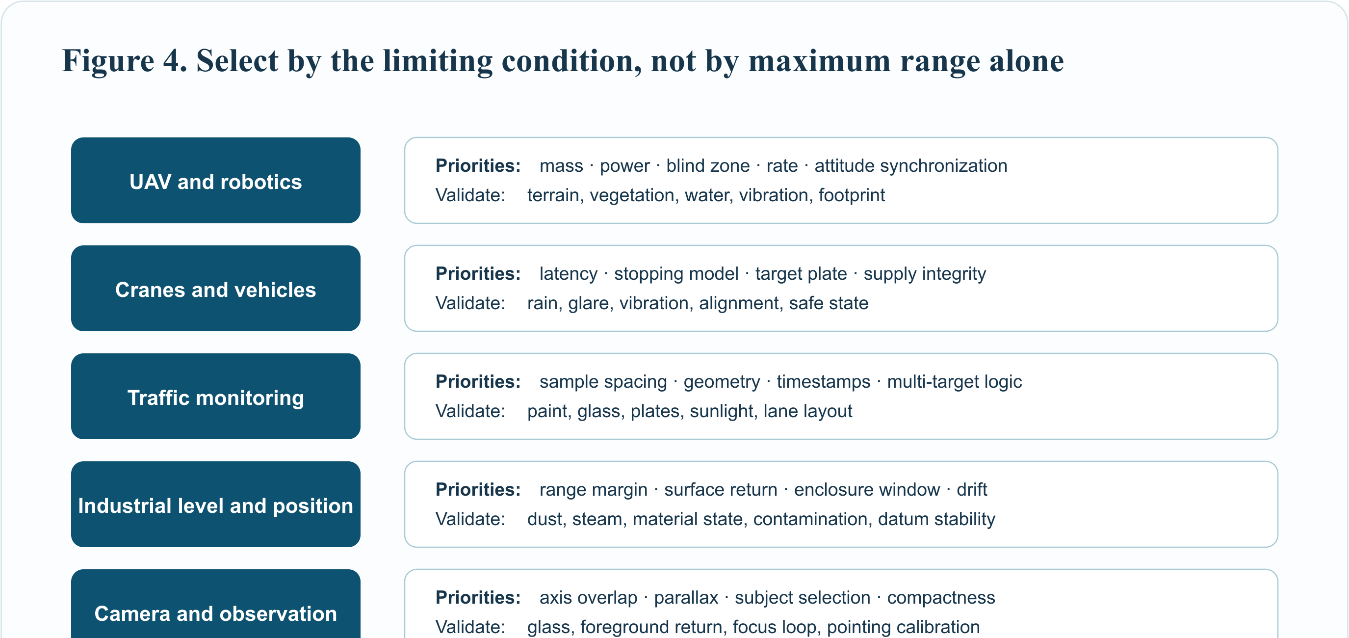
7. Application scenarios and the correct selection logic
7.1 UAV altitude hold, terrain following, and payload ranging
For low-altitude control and obstacle detection, compact mass, power, close blind zone, footprint, and update rate often matter more than maximum headline range. A 100-200 Hz compact module can supply frequent observations to an autopilot, but the designer must consider attitude, rotor vibration, ground reflectivity, vegetation, water, and sloped terrain. For long-range UAV pods, the 300-1500 m family offers a narrow approximately 4 mrad field specification and adaptive high/low measurement rate. Payload software should use precise timestamps and reject frames inconsistent with inertial and pointing geometry.
7.2 AGV, AMR, robot, and shuttle-vehicle safety
A single-point laser distance sensor can monitor a defined corridor, docking axis, lift height, or stopping zone. It is not automatically a safety-rated protective device. Functional safety requires a system architecture, diagnostic coverage, safe-state logic, validated field geometry, and applicable machinery standards. Useful engineering tests include dark and bright targets, floor transitions, black rubber, glossy packaging, cross traffic, sunlight through doors, dust, vibration, and multiple sensors operating nearby.
7.3 Overhead cranes, tower cranes, and carriage positioning
High-rate DToF ranging can track trolley travel, hook-zone clearance, opposing crane separation, or end-stop approach. The 50-600 m industrial modules are relevant where 9-36 V input, compact integration, and 1 kHz-class updates are required. The final system must consider structural vibration, cable motion, rain, fog, target plate size, reflectivity, alignment drift, and safe braking distance. A dedicated target plate can make the optical interface more deterministic than an uncontrolled steel surface.
7.4 Traffic warning and vehicle presence
A high update rate can reduce the distance travelled between measurements and support speed estimation from a time sequence. A two-point or multi-sensor layout can provide direction and lane logic. Vehicle paint, windows, license plates, retroreflectors, rain spray, low sun, and road geometry should all be included in acceptance trials. Do not derive an enforcement-grade speed claim from range rate alone; calibration, timing traceability, geometry, and jurisdictional requirements are separate.
7.5 Conveyor, port, tunnel, and industrial process monitoring
Distance sensing can identify material position, carriage location, pile level, portal clearance, or intrusion into a defined beam. Long conveyors and tunnels introduce dust, steam, repetitive structures, and mounting vibration. Port environments add salt, rain, glare, and large metal surfaces. A field enclosure must protect the optical window while avoiding a near-field return into the receiver. Window material, wedge, anti-reflection coating, thickness, and spacing should follow model-specific integration guidance.
7.6 Wind turbine, blade encroachment, landslide, and displacement monitoring
High-rate measurements can capture dynamic displacement and allow later down-sampling for trend analysis. The design should retain raw timestamps, validity flags, and environmental metadata. A stable reference surface and mechanical datum are essential; otherwise thermal expansion or mount movement can be mistaken for target displacement. For blade or rotating-object monitoring, synchronize range data with rotational phase and verify that the beam footprint stays on the intended surface throughout motion.
7.7 Camera autofocus, pan-tilt-zoom, and observation instruments
A compact 905 nm sensor can provide an initial subject-distance estimate for lens control or target tracking. The optical axes are usually offset, so parallax and overlap must be calibrated over range. Highly reflective foreground objects or glass can produce a distance different from the selected visual target. The camera should treat range as one cue and combine it with image focus metrics, detection confidence, and region-of-interest geometry.
7.8 Level, stockpile, and fill-height measurement
For bins, silos, and open piles, a non-contact laser can reduce mechanical wear. The surface may be granular, moving, dusty, wet, angled, or partially shadowed. High-rate data helps detect filling transients and enables robust temporal filtering, but maximum range on a flat reflector does not predict a dark powder at an oblique angle. Validate the actual material across expected fill states and contamination of the window.
8. Optical and mechanical integration
The module should be mounted to a stable datum with controlled pitch, yaw, and roll. Do not clamp the optical assembly in a way that deforms its housing. Provide strain relief for the cable and maintain the specified supply at the connector during transmit activity. Where the host uses a protective window, keep the window clean, tilted or wedged as required to direct specular return away from the receiver, and close enough to the optical face to limit internal reflections without mechanical interference.
Biaxial transmit and receive optics may have a range-dependent overlap region. A window or bezel can clip one path before the other, producing near-field loss or a discontinuity rather than a simple constant attenuation. Test the complete enclosure from the minimum required distance to maximum range. If the system requires a minimum blind zone, verify it after the final mechanical design, not only with the bare module.
Electromagnetic and electrostatic design also matters. Route power and serial lines away from switching nodes and motors, provide a defined ground return, and follow ESD handling precautions. When several 905 nm sensors share a scene, test optical interference under realistic timing. Random dropouts may be caused by another emitter rather than by the target.
9. Interface implementation and defensive parsing
A reliable driver treats the serial stream as untrusted framed data. It searches for the documented header, reads the complete frame, verifies the checksum, decodes little-endian fields, converts the documented unit, checks sentinel values, and assigns a local timestamp. It never converts an incomplete frame into a distance. A watchdog marks the measurement stale when the elapsed time exceeds the allowed interval, especially for adaptive-rate modules.
At 1 kHz, logging every frame is useful during validation but may be unnecessary in production. A practical architecture keeps a short circular buffer, stores exception windows around invalid or rapidly changing measurements, and reports statistical health counters. These include valid-frame ratio, checksum errors, out-of-range frames, inter-frame interval, minimum and maximum distance, and rejected innovations. Such evidence makes field faults diagnosable.
10. A measurement uncertainty and validity model
The output should be modeled as a value plus state, not as an unconditional scalar. A minimal record includes distance, timestamp, age, configured or observed rate, validity, and reason for rejection. Where the module exposes only distance, the host can still infer missing frames, out-of-range sentinels, impossible jumps, and stale data. It should not invent a numerical confidence percentage without a validated mapping.
System acceptance should separate offset error, repeatability, linearity, warm-up drift, temperature drift, dynamic lag, and availability. For each target class, record reflectivity or at least a reproducible material description, size, incidence angle, distance, ambient illumination, weather, and window condition. Use a calibrated reference method appropriate to the claimed accuracy.
11. Recommended verification plan
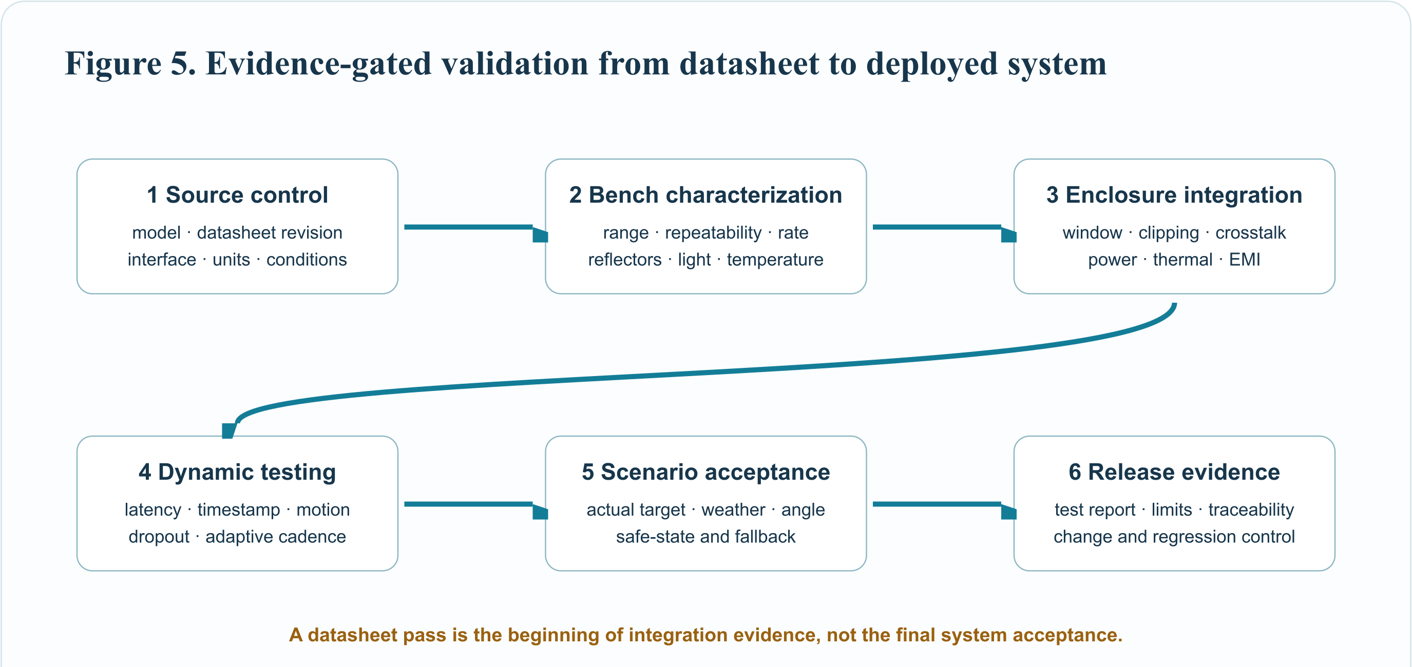
Source and configuration. Freeze the exact module model, datasheet revision, firmware identifier, baud rate, output mode, supply voltage, cable, enclosure, and optics. Record the unit serial number. Do not mix results from similar housings or model names.
Static range grid. Test several distances across the working interval with at least a high-return and low-return target. Include the minimum operational distance, threshold ranges where accuracy definitions change, and the maximum range required by the application. At every point record mean error, standard deviation or robust dispersion, valid-frame ratio, and observed frame interval.
Ambient and target matrix. Repeat under dark indoor conditions, representative artificial lighting, sunlight directions, and the required environmental extremes. Use the actual window and target materials. Lux readings should be recorded but not treated as a complete near-infrared spectral measurement.
Dynamic tests. Move the target or sensor with traceable position and time. Measure step response, lag, overshoot introduced by host filtering, and dropout during fast reflectivity transitions. Confirm the distance travelled between valid samples at the worst closing speed.
Fault tests. Cover the window, disconnect the sensor, corrupt serial frames, brown out the supply, introduce invalid sentinels, heat the enclosure, and exceed the allowed frame age. Verify that the host moves to the documented safe or degraded state.
Production tests. Define an incoming inspection and end-of-line check that is short enough to run on every unit but sensitive to incorrect firmware, optical contamination, alignment shift, and interface faults. Keep a longer audit test for sampled units and after supplier or process changes.
12. Common errors in specifications and purchasing
Comparing maximum ranges without target conditions. A 90% reflector and a 10% target can produce very different limits. Ask for target size, reflectivity, angle, illumination, and detection criterion.
Treating resolution as accuracy. A sensor can output 1 mm increments without being accurate to 1 mm. Use the correct accuracy and repeatability definitions from the controlled datasheet.
Assuming every frame arrives at the headline rate. Adaptive products may reduce rate on weak returns. Fixed-rate products may still deliver invalid frames. Specify valid-frame availability and maximum acceptable age.
Ignoring the enclosure window. A clear-looking window can introduce loss, ghost returns, clipping, temperature shift, or contamination. Validate the finished optical stack.
Using a module safety statement as finished-product certification. Evaluate the accessible emission and use conditions of the final product under the applicable edition of IEC 60825-1 and any product-specific standard.
Choosing maximum rate when the link budget requires integration. More frequent output does not create photons. Select the rate that produces a trustworthy measurement for the actual scene and control need.
13. How to select the right ERDI module
Start with the minimum and maximum operational distances, not the catalog maximum. Define target reflectivity and size, beam footprint, ambient environment, platform speed, required valid-frame interval, accuracy, repeatability, supply rail, interface, mechanical envelope, temperature, window, and safety obligations. Then select the smallest verified module that meets the complete set with margin.
For compact robots, focusing, and low-altitude sensing, the 20 m 200 Hz and 50 m 100 Hz modules prioritize size, millimetre output resolution, low voltage, and UART/I2C integration. For faster industrial control, the 50-200 m H-series supports 1 kHz default operation and a 20 Hz-10 kHz published setting range on the relevant controlled datasheets. For longer scenes, the 300 m, 600 m, and 1500 m modules combine narrow-angle optics with 1 kHz/50 Hz adaptive output. The longer-range choice is justified only if its footprint, target return, optical alignment, and slower weak-return behavior fit the application.
ERDI can support OEM selection and integration around target definition, interface requirements, optical window constraints, mechanical structure, and output protocol. Customization should be controlled by a written specification and revalidated because changing appearance, structure, optics, firmware, or protocol can change system behavior. Visit https://erdicn.com or the linked product pages for current controlled information and an engineering inquiry.
14. References and authoritative sources
- National Institute of Standards and Technology, CODATA value: speed of light in vacuum, exact SI value 299,792,458 m/s.
- IEC, IEC 60825-1:2014 Safety of laser products Part 1, equipment classification and requirements. Confirm the applicable edition, amendments, and product standards for the target market.
- J. Dai et al., Requirements for Automotive LiDAR Systems, Sensors 22, 7532 (2022). Review of ranging principles, emitters, detectors, scanning, and safety requirements.
- G. M. Williams, Optimization of eyesafe avalanche photodiode lidar for automobile safety and autonomous navigation systems, Optical Engineering 56(3), 031224 (2017).
- onsemi, SiPMs in Direct ToF Ranging Applications, TND6254. Direct-ToF architecture, histogram accumulation, background, and ambiguity considerations.
- Y. Yang et al., Progress in Avalanche Photodiodes for Laser Ranging, review of detector architectures, timing uncertainty, and ranging applications.
- D. R. Reilly and G. S. Kanter, High speed lidar via GHz gated photon detector and locked but unequal optical pulse rates, Optics Express 22, 15718 (2014). Demonstrates the relationship between high speed, sensitivity, and ambiguity management.
- ERDI TECH LTD, current controlled model datasheets and product pages linked in Section 6. Product values in this article were checked against those model-specific sources.
Editorial scope. Equations and diagrams describe generic engineering principles and are not proprietary circuit disclosures. Product numbers are reported only with their stated test conditions. Final performance and compliance depend on the selected model, configuration, host optics, environment, target, firmware, and validation method.