

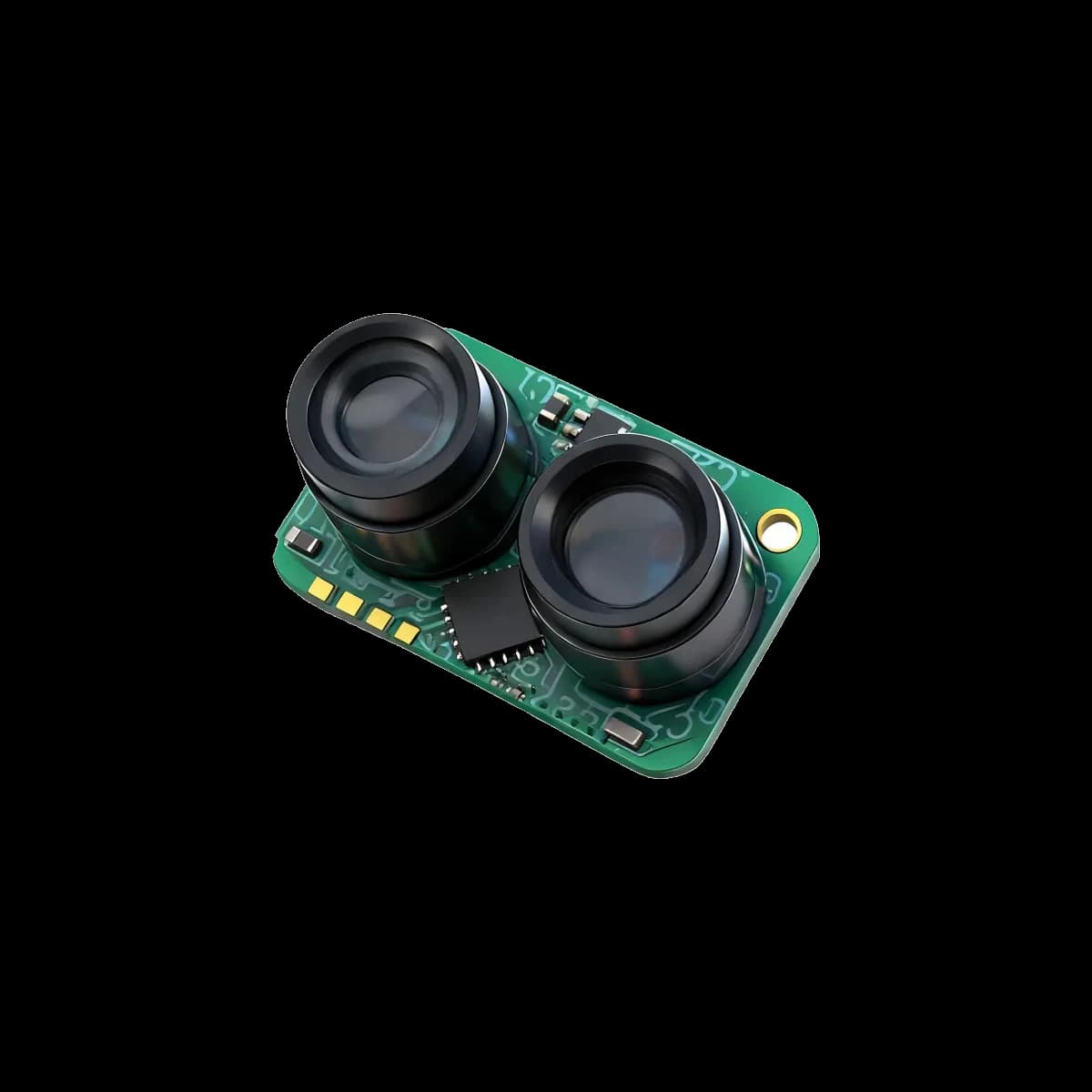
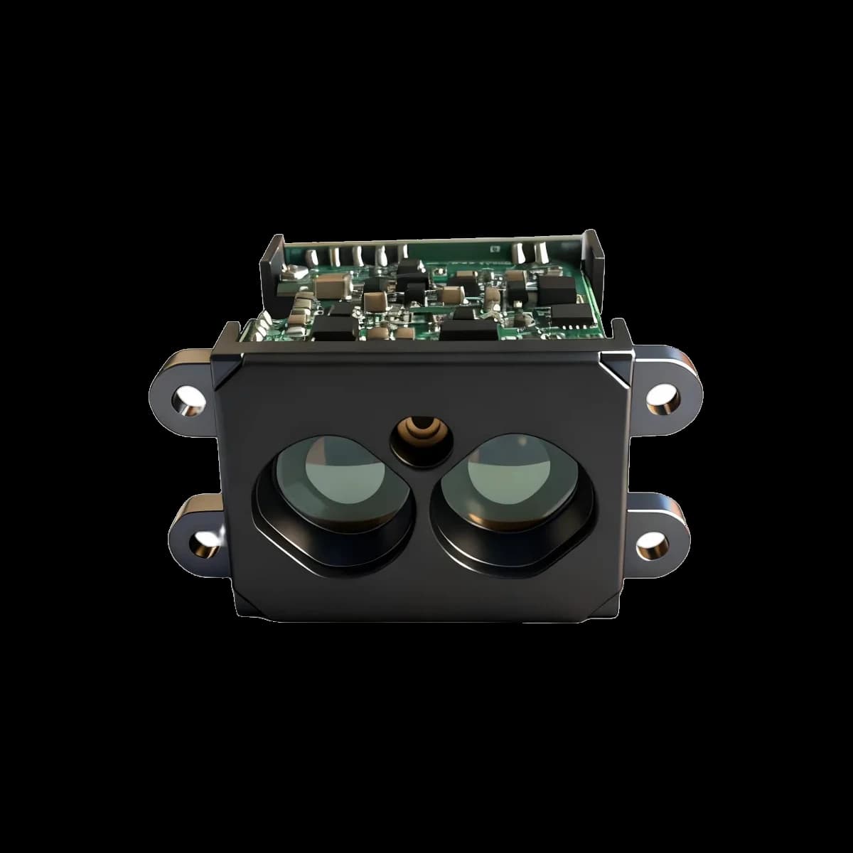
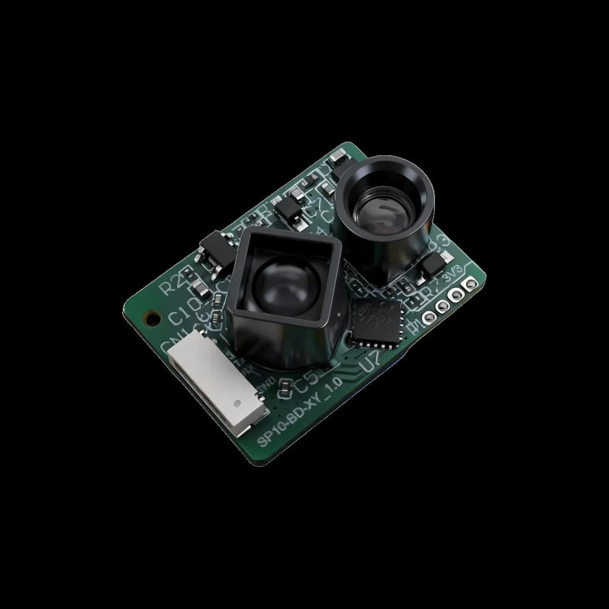
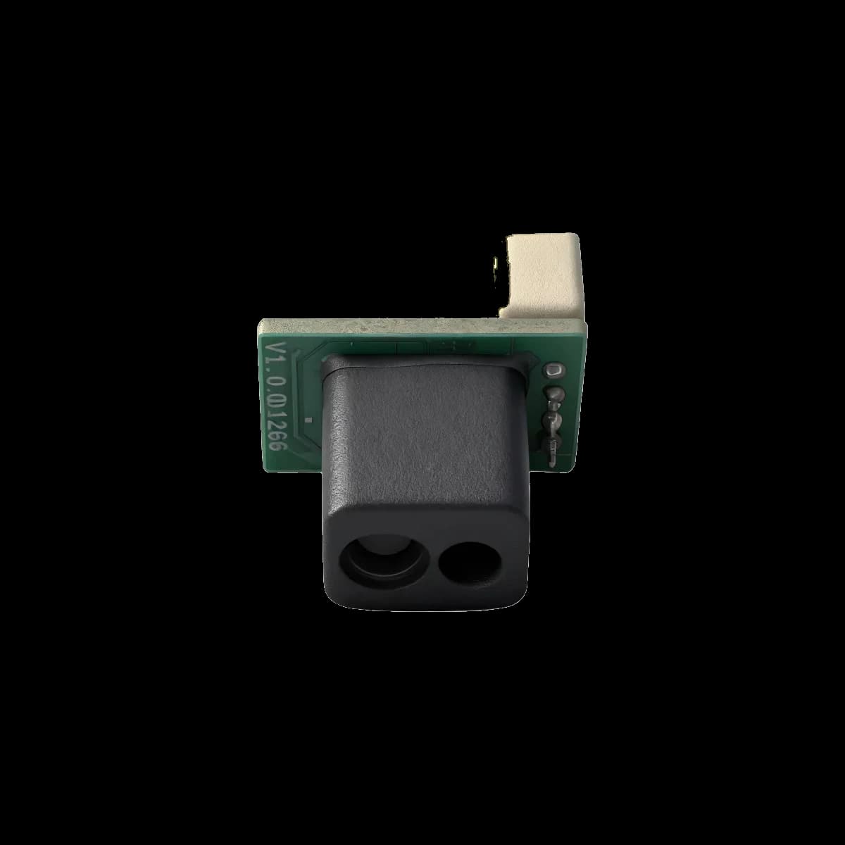
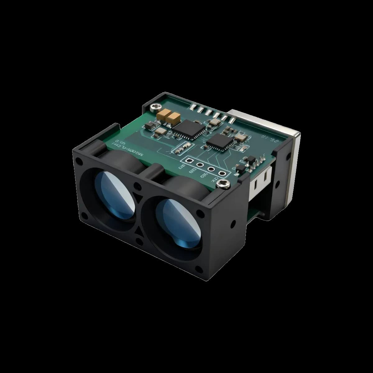
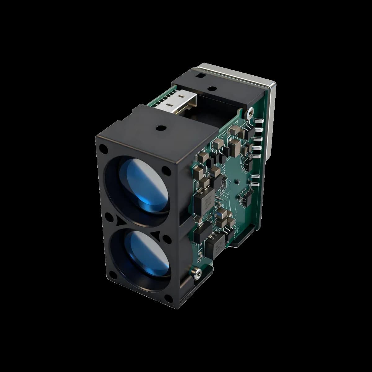
Detailed LRF50VB Specifications
Every value below is bound to the model source named on this page. Qualifiers and test conditions are retained; missing values are not inferred.
Basic ranging performance
| Parameter | Value | Source condition |
|---|---|---|
| Measurement range | 0.05-50 m (90% reflectivity); 0.05-20 m (10% reflectivity) | The two source values remain bound to their stated target reflectivity. |
| Measurement frequency | 100 Hz | Confirm against the controlled model document |
| Accuracy | ±5 cm (<5 m); 1% (≥5 m) | Confirm against the controlled model document |
| Repeatability | ±30 mm | Confirm against the controlled model document |
| Ambient-light immunity | 10 m at 60 klx | Confirm against the controlled model document |
| Reported resolution | 1 mm | Front-page feature statement; not an accuracy value |
Optical parameters
| Parameter | Value | Source condition |
|---|---|---|
| Central wavelength | 905 nm | Confirm against the controlled model document |
| Photobiological safety | Class 1 | Confirm against the controlled model document |
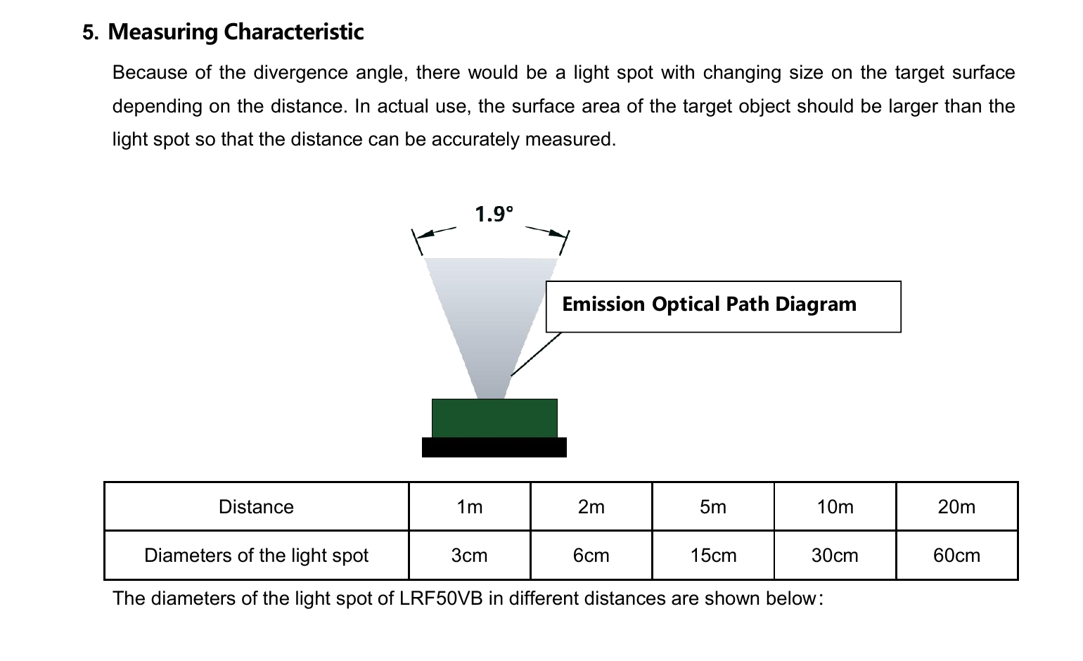
| Field of view | 1.9° | Confirm against the controlled model document |
| Wavelength for indication | N/A | Confirm against the controlled model document |
| Photobiological safety for indication | N/A | Confirm against the controlled model document |
Electrical and communication interface
| Parameter | Value | Source condition |
|---|---|---|
| Supply voltage | 3.3-5 V DC | Confirm against the controlled model document |
| Peak current | 5 V at 70 mA | Confirm against the controlled model document |
| Average current | 5 V at 40 mA | Confirm against the controlled model document |
| Average power consumption | 0.2 W | Confirm against the controlled model document |
| Communication interface | UART/IIC | Confirm against the controlled model document |
Mechanical and environmental
| Parameter | Value | Source condition |
|---|---|---|
| Protection level | N/A | Confirm against the controlled model document |
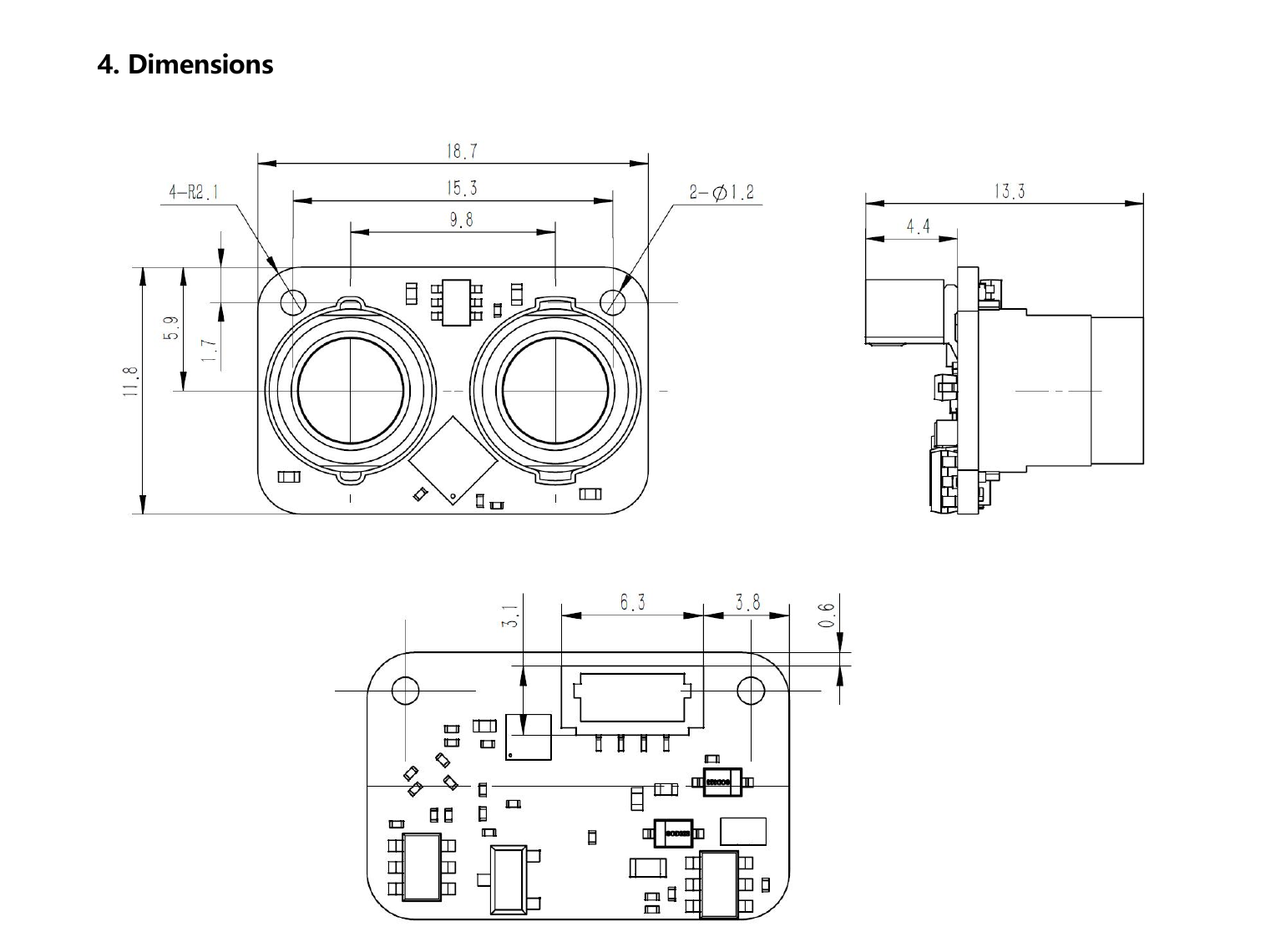
| Dimensions | 18.7 × 11.8 × 13.3 mm | Confirm against the controlled model document |
| Weight | 1.3 g | Confirm against the controlled model document |
| Operating temperature | -20°C to +60°C | Confirm against the controlled model document |
| Wire specification | 4-pin 1.0 mm terminal, 10 cm tinned stranded wires | Confirm against the controlled model document |
| Customization | Available in appearance / structure / output protocol | Confirm against the controlled model document |
Functional Description
The formal specification states a 100 Hz measurement frequency.
The formal specification lists UART/IIC as the communication interface.
The source describes flexible installation and expansion for drones, sweeping robots and industrial robots.
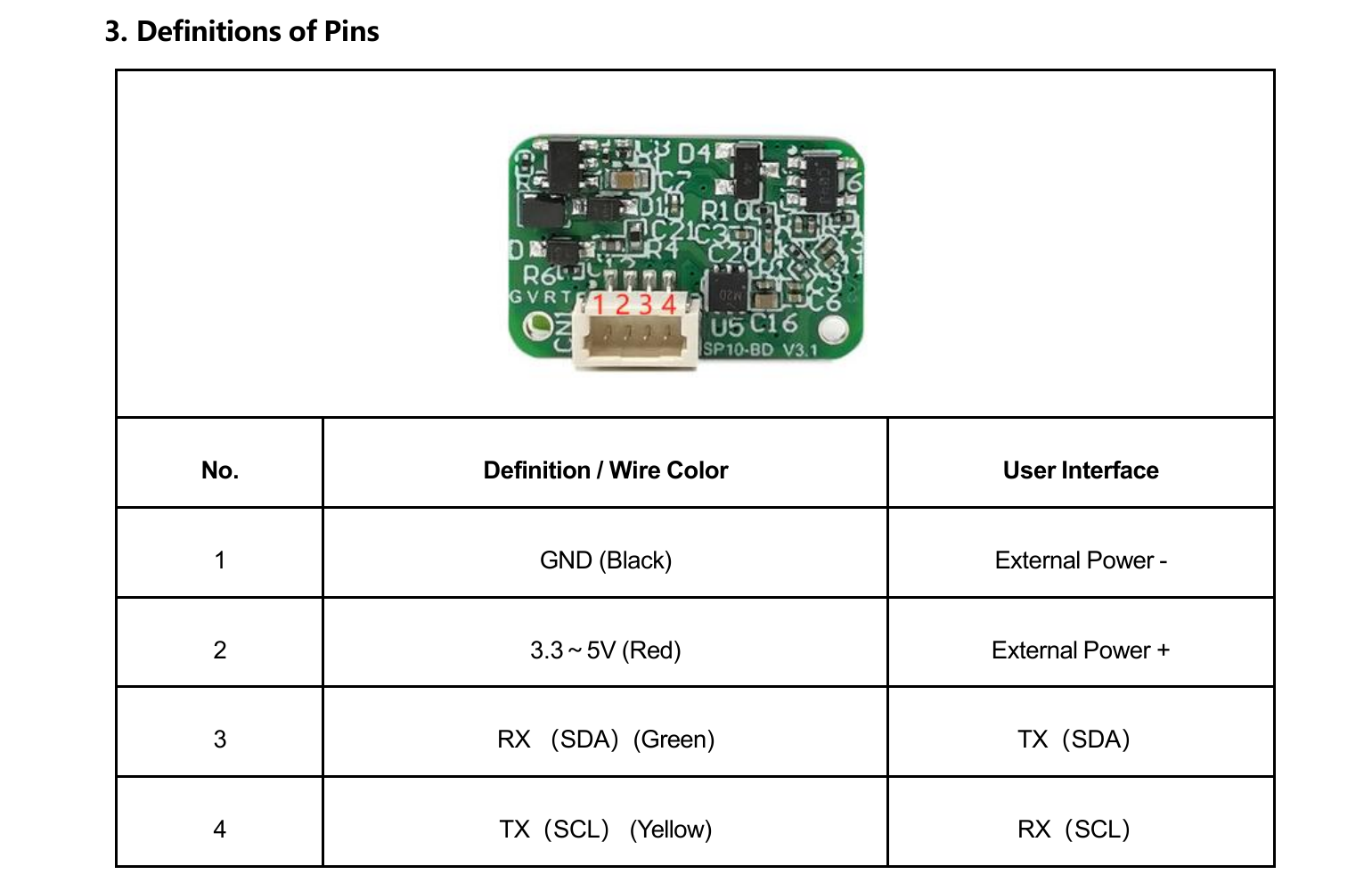
Electrical Interface Definition
Signal names and directions are transcribed from the model source.
| Pin | Signal | Source-stated function |
|---|---|---|
| 1 | GND (black) | External power negative |
| 2 | 3.3-5V (red) | External power positive |
| 3 | RX / SDA (green) | Host TX / SDA |
| 4 | TX / SCL (yellow) | Host RX / SCL |
Mechanical Dimension Drawing and Electrical Interface Diagram
These figures are extracted from the named model source without generative modification.
Direct Time-of-Flight Ranging
The LRF50VB model document identifies the product as direct time of flight (DToF). It determines distance from the delay between an emitted optical pulse and the accepted return.
Real performance also depends on target reflectivity and area, incidence angle, atmospheric attenuation, receiver aperture, background light, detector response, timing thresholds and contamination of the optical path.
What the verified data supports
These are traceable design inputs, not unsupported superlatives or guaranteed field outcomes.
Performance envelope
Measurement range: 0.05-50 m (90% reflectivity); 0.05-20 m (10% reflectivity) · Accuracy: ±5 cm (<5 m); 1% (≥5 m)
Timing and output
Measurement frequency: 100 Hz · Reported resolution: 1 mm · Repeatability: ±30 mm
Electrical integration
Supply voltage: 3.3-5 V DC · Communication interface: UART/IIC · Average power consumption: 0.2 W
Mechanical integration
Dimensions: 18.7 × 11.8 × 13.3 mm · Weight: 1.3 g · Operating temperature: -20°C to +60°C
Source-stated application context
Application labels indicate where the source proposes evaluation; they do not prove fitness without system testing.
- Drone altitude holding and obstacle avoidance
- Robot obstacle avoidance
- Industrial-grade light curtains
- AGV obstacle avoidance
- High-speed measurement and safety monitoring in traffic and industrial automation
Confirm before selection
- Define target size, reflectivity, incidence angle and required detection probability.
- Reproduce sunlight, visibility, weather and optical-window conditions in acceptance testing.
- Verify voltage tolerance, peak current, grounding, interface levels, baud rate and connector revision.
- Separate accuracy, repeatability and displayed resolution in host requirements.
- Confirm mounting datum, boresight, field of view, enclosure sealing and thermal path.
- Assess accessible emission and labeling again after integration into the finished equipment.
Questions to resolve before design release
Does the maximum stated range apply to every target?
No. Use the reflectivity and environmental conditions shown beside the range row. Smaller, darker, oblique or partially obscured targets and degraded visibility can reduce received signal.
Are resolution, repeatability and accuracy interchangeable?
No. Resolution is the reporting increment, repeatability describes variation under repeated conditions, and accuracy describes closeness to the reference distance under the stated test method.
Is the finished product automatically Class 1?
No. A module-level source statement does not replace the accessible-emission and failure-condition assessment of the finished equipment, its window, controls, service access and labeling.
Which documents control wiring and interface release?
The ordered connector drawing, pin definition and approved interface document control the design.
Product evidence and general technical context
The model PDF controls product claims. Public references support only the general engineering explanations and must not be used to infer a missing model value.
- LRF50VB Specification V3.0Model-specific product evidence; SHA-256 is shown above.
- System Design of a Pulsed Laser RangefinderOptical Engineering 30(3), 1991 - link budget, background, noise, detection and range error.
- The Short-Range, High-Accuracy Compact Pulsed Laser Ranging SystemSensors 22(6), 2146, 2022 - pulsed-ToF equation, timing error, reflectivity and temperature effects.
- Laser system range calculations and the Lambert W functionApplied Optics 48(4), B1-B7, 2009 - range performance versus atmospheric transmission, target and system parameters, and threshold SNR; its 1.06 µm example is general context, not ERDI model data.
- Monostatic all-fiber rangefinder systemApplied Optics 54(25), 7687-7694, 2015 - a measured case study of shared-aperture geometry and receiver-recovery loss; it does not establish an ERDI model limit.
- Light Transmission in Fog: The Influence of Wavelength on the Extinction CoefficientApplied Sciences 9(14), 2843, 2019 - measured and modeled wavelength-dependent fog attenuation.
- IEC 60825-1:2014Laser-product classification and accessible-emission requirements; final equipment requires system-level assessment.