

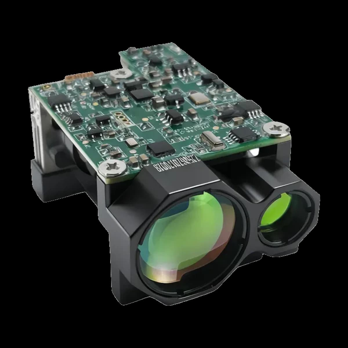
Detailed LRF0310C Specifications
The technical material below is retained for this model only. Do not transfer a range, pulse, interface, mechanical or safety value from another 1535 nm product.
Specifications
LRF0310C is a 1535 nm pulsed distance-measurement module. Its assigned laser source is ER100; receiver-component data below come from the supplied APD-A13B001 R01 document. The three specification levels describe different assemblies and measurement conditions.
1. LRF0310C module specifications
Source clarifications
The current PDF range cell states a 2.3 × 2.3 m reference target, while its parenthetical condition names a 2.3 × 4.6 m board or vehicle. The row heading gives visibility ≥5 km; the cell gives ≥8 km and relative humidity ≤60%. These source descriptions are not combined into a new acceptance condition. Its interface description cells are also misaligned with several pin names; consult the confirmed connector record before wiring.
|
Project |
Performance Indicators |
|
Model |
LRF0310C |
|
Laser Wavelength |
1535±5nm |
| Module laser-safety statement | Class I stated in the module document. Final accessible-emission classification applies to the complete configuration. |
|---|---|
|
Divergence Angle |
≤0.6 mrad |
|
Laser Energy |
≥100 μJ |
|
Launch Lens Diameter |
Φ8 mm |
|
Receiver Lens Diameter |
Φ16 mm |
| Measuring range — current PDF record | ≥3000 m. Source names a 2.3 × 2.3 m reference target; parenthetical: 2.3 × 4.6 m board or vehicle, relative humidity ≤60%, visibility ≥8 km. Row heading: reflectance 30%, visibility ≥5 km. See the source clarification below; target and visibility descriptions are inconsistent. |
|
Minimum Range |
≤15 m |
|
Ranging Frequency |
Single, 1Hz ~10Hz |
|
Number of multi-target detections |
Up to 3 targets |
|
Ranging Accuracy |
±1 m |
|
Range Resolution |
≤0.1 m |
|
Precision Rate |
≥98% |
|
False Alarm Rate |
≤1% |
|
Supply Voltage |
4.5V~16V |
|
Standby power consumption |
≤ 0.6W |
|
Average power consumption |
≤1.5W@1Hz |
|
Peak Power Consumption |
≤7W@12V |
|
Weight |
≤32±1 g |
|
Dimension (L×W×H) |
48mm×30.5mm×21mm |
|
Operating Temperature |
-40~+70 ℃ |
|
Storage Temperature |
-55~+75 ℃ |
|
Impact Resistance |
Meet the MIL-STD-810G testing standard |
|
Vibration Resistance |
Meet the MIL-STD-810G testing standard |
|
Pin |
Definition |
Description |
Cable color |
|
P-1 |
VIN+ |
Power supply, 4.5–16V |
|
|
P-2 |
VIN- |
Power supply, ground |
|
|
P-3 |
POWER_ON |
Module power switch, TTL_3.3V level; |
|
|
P-4 |
UART_TX |
Module on (>2.7V), module off (<0.3V) |
|
|
P-5 |
UART_RX |
Serial port transmitting end, TTL_3.3V level |
|
|
P-6 |
GND |
Serial port receiving end, TTL_3.3V level |
Model-specific mechanical and interface drawings
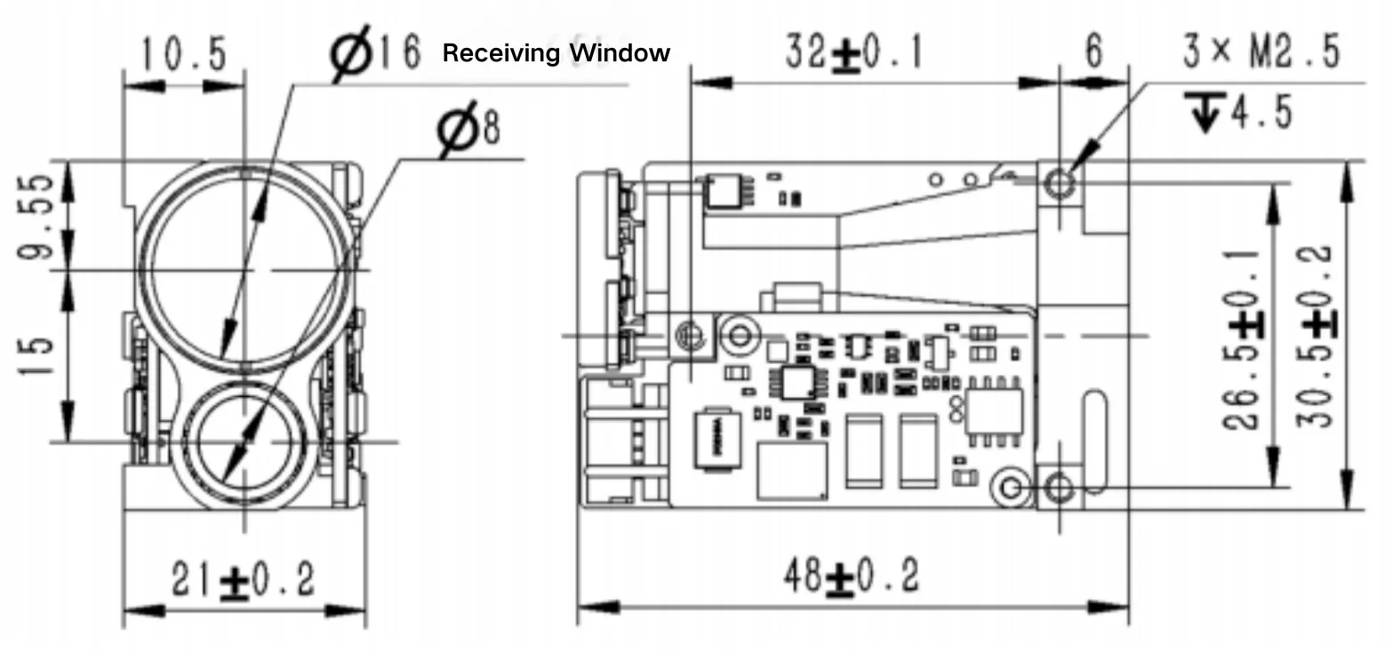
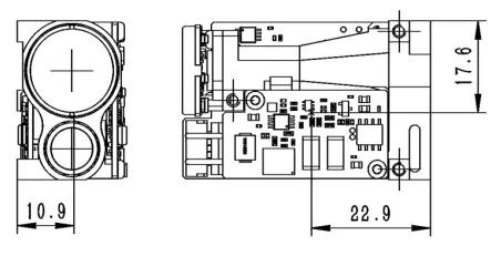
2. ER100 source-laser specifications
| Parameter | Value |
|---|---|
| Optical wavelength | 1.54 µm in the component table; 1535 nm in its description |
| Pulse energy | ≥100 µJ |
| Optical pulse width | 6 ns |
| Drive pulse width | ≤2.4 ms |
| Repetition rate | 1–10 Hz |
| Pulse stability | 10% (definition/statistical method not stated) |
| Raw beam diameter | 0.3 mm |
| Initial beam divergence | ≤8 mrad |
| Transverse mode | TEM00 |
| Operating / storage temperature | −40 to +65 °C / −55 to +75 °C |
| Package dimensions / mass | 21 × 8 × 6.8 mm / 7 g |
| Component electrical entry | 2 V, 8 A |
| Shock / vibration entries | 1500 G, 0.5 ms / 20–2000 Hz, 20 G |
| Stated service life | ≥1 million shots in the specification table; introduction states 10 million without resolving the difference |
The electrical entries describe the component drive, not the module supply input. Drive conditions and pulse-width definitions must follow the component document and the individual factory record. An optical pulse-width value is not a pump-drive duration.
3. APD-A13B001 receiver-component specifications
Small screens: swipe the table horizontally to read all measurement conditions.
| Parameter | Value | Measurement condition / scope |
|---|---|---|
| Device / active diameter | APD-A13B001 R01 / 200 µm | Supplied APD200 document, p1 |
| Detector spectral response interval | 800–1700 nm | Detector response; not the filter passband |
| Responsivity | 0.9 A/W minimum; 1.0 A/W typical | λ = 1550 nm; incident power = 1 µW; M = 1 |
| Dark current | 8 nA typical; 50 nA maximum | VR = VBR − 3 V; incident power = 0 |
| Multiplication factor | M ≥10 / M ≥30 | λ = 1550 nm; 1 µW; respectively VBR − 3 V / VBR − 1 V |
| −3 dB bandwidth | 0.6 GHz minimum; 1.25 GHz typical | M = 10; RL = 50 Ω |
| Breakdown voltage | 35–50 V | Reverse current = 10 µA; incident power = 0 |
| Capacitance | 1.8 pF typical; 2.0 pF maximum | VR = VBR − 3 V; f = 1 MHz |
| Breakdown temperature coefficient | 0.05 minimum / 0.11 typical / 0.15 maximum V/°C | Reverse current = 10 µA; dark; −55 to +85 °C |
| Operating / storage temperature | −40 to +85 °C / −55 to +125 °C | Component absolute-maximum table; not module environmental ratings |
| Maximum bias | VBR | Absolute maximum, not a recommended operating setpoint |
| Maximum forward / reverse current | 5 mA / 3 mA | Absolute maximum ratings, not continuous design targets |
| Filter centre wavelength | 1535 ±5 nm | Supplied filter table, p3 |
| Filter FWHM | <37 nm | Full width at half maximum |
| Transmission at centre wavelength | >90% | Filter specification, not total receiver throughput |
| Blocking specification | T <1%; source lists 400–1750 nm | Stop-band/transition edges are not numerically defined; the stated blocking span is not a guarantee at every wavelength. |
| Optical surface quality | 60/40 | Source label: surface quality; not a transmission value |
Responsivity is measured at 1550 nm; a value measured there is not silently relabeled as a measured 1535 nm value. Absolute maxima are stress limits. The filter document includes an illustrative spectrum, but does not define numerical transition edges or off-axis performance. No additional spectral guarantee is inferred.
Model-specific conditions and limits
Conditions are retained only when the source states them. They are not reconstructed from a nominal range or wavelength.
Operating conditions
Read a range value together with its test case
Target dimensions, surface reflectance and atmospheric visibility are part of the range specification. The beam may partly miss a small object, illuminate a sloped surface or return from several depths. A high-reflectance building result cannot establish the same distance to a smaller or darker object. Humidity and temperature conditions shown in a source table describe that test; visibility is not interchangeable with a guaranteed transmission percentage.
Measurement rate and electrical conditions
Measurement rate is the number of reported measurement opportunities per second. It is separate from optical pulse duration, receiver bandwidth and the time required for an individual return. Read operating power at the frequency and supply printed beside it. Peak power describes a different electrical requirement from average power; an average figure alone does not characterize supply transients.
Environmental and measurement context
A module temperature rating, laser-component temperature range and APD maximum rating describe different assemblies. Likewise, a named vibration standard does not disclose every method, mounting condition or acceptance threshold. Range repeatability, reported resolution and absolute accuracy are different quantities: a fine numerical display increment does not establish the error of the complete measurement.
Pulsed Time-of-Flight Ranging
Technical principle
A pulse, a return and a measured interval
Pulsed time-of-flight ranging measures elapsed time between an optical launch reference and a detected echo. The basic relationship is R = vΔt/2, where v is the speed of light in the propagation medium. The factor of two accounts for the outward and return journeys. The familiar expression using c treats propagation as approximately in air/vacuum; absolute metrology also considers refractive index and calibrated internal delays.
The measurement chain contains a pulsed source, transmit optics, an illuminated surface, collection optics, spectral filtering, a detector and timing electronics. ER100 supplies optical pulses. The module's output beam is described by its own optical specification after integration. A nanosecond laser pulse is not the same quantity as a millisecond pump-drive pulse or a hertz measurement rate.
Initial divergence and the integrated beam
A bare source has its own beam diameter and divergence. Collimating and expanding optics alter the relationship between beam size and angular spread. Therefore the component's initial divergence and the assembled module's transmitter divergence belong in separate rows. Finite beams still diffract, and real optics add aberrations, alignment error and clipping. A quoted angular value also needs a full-angle/half-angle convention and a beam-width definition before it supports a numerical footprint calculation. Those definitions are not invented where the product record omits them. Newport's optics explanation provides the general context.
Why the same laser can appear in different range classes
The laser source is one contributor to system performance. At a fixed, uniform irradiance at the receiver entrance, a circular unobscured collecting aperture has area A = πD²/4. With equal throughput and no clipping, collected optical power is proportional to that area. A larger receiver lens can therefore collect more of the available return. This is an area relationship under stated assumptions, not a range multiplier and not a test result for this product.
The return reaching that aperture also depends on transmitted energy, beam spread, object size and reflectance, surface orientation, atmospheric attenuation and optical transmission. Increasing collection area may collect additional background light as well. Receiver field of view, throughput, detector response and the decision process determine how much useful information remains. Consequently, models sharing ER100 can have different conditional range specifications, and their ranges should be compared using equivalent target and weather conditions.
APD conversion, filtering and timing
The supplied InGaAs APD generates photocurrent and provides internal avalanche multiplication. Its responsivity at M = 1 describes conversion before multiplication; the gain values describe a specified reverse-bias condition. Internal gain accompanies multiplication noise. Dark current, capacitance and bandwidth also matter, so the maximum tabulated gain is not automatically the best operating point. The specified gain conditions below breakdown describe linear APD operation, not evidence of single-photon Geiger-mode operation. Hamamatsu's detector guide explains these distinctions.
The narrowband filter transmits the useful wavelength region while rejecting specified out-of-band light. It does not reject background that lies inside its passband. Its centre transmission is not the throughput of the lens, window, filter and detector assembly together. A detector bandwidth measured at 50 Ω likewise does not specify the installed amplifier bandwidth or the finished rangefinder's accuracy.
Short distances, long distances and processing
At short distances, the return arrives near the launch event; optical overlap, prompt scatter and receiver recovery can limit the usable minimum distance. A strong close return can also exceed the linear region. At long distances, reduced return strength makes background, noise and signal discrimination more significant. These are different mechanisms, so good long-range performance does not imply a zero blind zone or a guaranteed result at every shorter distance.
In a threshold-based timing receiver, changes in pulse amplitude can shift the threshold-crossing time, called time walk. Calibration, multiple-return discrimination and signal estimation are general approaches discussed in the literature. Signal estimation and timing correction depend on the receiver architecture; no specific firmware method is claimed without a model-specific record. Reported multi-target capability alone does not disclose the underlying algorithm. Kurtti, Jansson and Kostamovaara examine receiver/TDC timing behavior in their own research hardware.
Pulse energy describes emitted energy per pulse; its effect cannot be separated from pulse width, divergence, optical losses, receiver threshold and the stated target/atmosphere conditions. It is not a substitute for a model-specific near- or long-range acceptance test.
Source-stated application context
Application labels indicate evaluation context, not automatic fitness for a finished system.
Applications
LRF0310C can be evaluated as a distance-sensing component in civilian instruments that can use its documented measurement conditions, dimensions and electrical interface.
Survey and infrastructure inspection
A range reading can accompany photographs or inspection records of buildings, bridges and outdoor assets. The distance is a line-of-sight measurement to a detected surface; it is not automatically a coordinate, elevation or complete survey solution. Surface size and reflectance must match the intended measurement task.
Industrial and robotic observation
Distance information can supplement an industrial camera, mobile inspection robot or fixed observation instrument. Minimum range, update rate and missing-return behavior matter as much as the headline maximum range. Suitability for protective or collision-prevention functions requires evidence beyond ordinary product ranging specifications.
Environmental and site monitoring
Fixed-point instruments can use repeated distance observations to document a selected surface or site feature. Rain, fog, changing surface moisture and intervening objects can change the accepted return; the result should retain its timestamp and measurement status.
For compact instruments, compare the listed envelope, mass and rate-dependent power with the available space and operating cycle. A module range reading alone does not constitute a complete navigation, surveying or safety system.
Confirm short- and long-distance acceptance conditions
- Define minimum distance, target material, reflectance, size and incidence angle.
- Check receiver recovery, optical-axis overlap and strong-return handling at the intended near limit.
- Verify supply tolerance, peak current, grounding, interface levels, connector and timing with the ordered revision.
- For long-distance acceptance, state target geometry, visibility, weather, background and required detection probability.
- Test with the installed window, boresight, field of view, enclosure and thermal path rather than a bare module alone.
- Evaluate accessible emission, labels and failure conditions again for the finished laser product under IEC 60825-1.
Questions to resolve before design release
FAQ
Which laser source is associated with LRF0310C?
The product configuration supplied for this page identifies ER100. Its component specification is shown separately from the module specification. The detector reference is APD-A13B001 R01 from the supplied APD200 document.
Why can a smaller object have a shorter specified range?
The beam can cover an area larger than the object, so only part of the illumination contributes a useful return. Surface reflectance, angle and weather further change the returned signal. Compare the complete target-conditioned test case.
Does a larger receive lens imply proportionally longer range?
At equal incident irradiance and optical throughput, collecting area scales with the square of clear diameter. Distance performance also depends on the return path, target and noise. The aperture-area ratio is therefore not a range ratio.
What is the difference between raw and module divergence?
Raw divergence belongs to the source before the module optics. The module figure belongs to the integrated transmitter. Optical collimation changes beam diameter and angular spread; use each value only at its specified reference plane.
Is range resolution the same as ranging accuracy?
Resolution describes the increment or separation represented by the output. Accuracy concerns departure from the true distance under defined conditions. Repeatability describes variation among repeated readings. These terms cannot substitute for one another.
Why is there a minimum range?
Very early returns can overlap prompt optical/electrical signals or arrive while the receiver is recovering. The transmit and receive paths may also have limited overlap nearby. The published minimum is a module property, not something inferred from laser energy.
What does multi-target reporting mean?
Where the model record specifies it, the output can contain more than one accepted distance from a measurement scene. It does not imply that every object is detected or that two arbitrarily close surfaces can always be separated. Use the documented model count and reporting behavior.
Does higher APD gain always improve the result?
Multiplication increases photocurrent but introduces excess noise; dark current and receiver noise also contribute. The optimum system condition cannot be selected from gain alone. The APD table provides component measurements, not a recommended user-adjustable bias setting.
Does a narrowband filter remove all sunlight?
It suppresses light in its specified blocking regions. Sunlight and other light inside the passband can still reach the detector. Centre transmission and bandwidth must be considered with the receiver field of view and total optical transmission.
Does a higher update rate make each reading more accurate?
A higher rate supplies more measurement opportunities per second. It does not by itself establish smaller absolute error. Power, temperature, scene motion and the model measurement mode can affect the usable operating point.
Can a component energy figure replace the module energy figure?
Each table applies to a different assembly. A minimum marked ≥ is not an upper energy limit, and a module may carry a separately specified higher minimum. A value without an inequality is not silently converted into a guaranteed minimum. Neither value should be copied into the other table without assembly-level evidence.
Why can the same surface sometimes produce no reading?
A return may be too weak, obscured or outside an accepted measurement condition. A surface can also redirect light away from the receiver. A missing or invalid reading must retain its status instead of being treated as a valid zero distance.
Is 1535 nm itself a laser-safety classification?
No. Wavelength affects the applicable exposure evaluation, but classification concerns accessible emission from a defined product. Where a module document states a rating, it applies to the described configuration; additional optics, controls and housings belong to the final product assessment under IEC 60825-1.
Product evidence and general technical context
The model PDF controls model claims. Public references below explain general engineering principles only.
References
- LRF0310C module datasheet: model specifications, conditions and drawings. The module table is based on this model's source record.
- ER100 laser datasheet: standalone source parameters; optical pulse, drive pulse and source/module quantities remain distinct.
- APD-A13B001 R01, “200 µm InGaAs APD PIN Photodiode”, supplied as APD200 (1).pdf: p1 electrical/optical characteristics and absolute ratings; p3 filter specification. It is component evidence rather than a range test report.
- S. Kurtti, J. Jansson and J. Kostamovaara, A CMOS Receiver–TDC Chip Set for Accurate Pulsed TOF Laser Ranging, IEEE Transactions on Instrumentation and Measurement 69(5), 2208–2217 (2020; online 2019), DOI 10.1109/TIM.2019.2918372. Primary research on timing electronics; its results are not LRF0310C measurements.
- Hamamatsu Photonics, Guide to detector selection: detector conversion and internal multiplication concepts. No Hamamatsu device values are substituted for APD-A13B001.
- Newport, Beam Focusing and Collimating: reference planes, beam-size/divergence conventions and general collimation principles. Its example optical assemblies are not this module's design.
- NASA Langley, LITE instrument: a primary institutional example of a telescope collecting scattered light into receiver optics; no LITE performance or architecture is attributed to this product.
- IEC 60825-1:2014, Safety of laser products — Part 1: equipment classification and requirements. The standard's existence is not evidence of certification for an unassessed final assembly.
- ERDI LRF0310C model PDFModel-specific technical evidence.
- System Design of a Pulsed Laser RangefinderOptical Engineering 30(3), 1991 - link budget, background, noise, detection and range error.
- The Short-Range, High-Accuracy Compact Pulsed Laser Ranging SystemSensors 22(6), 2146, 2022 - pulsed-ToF equation, timing error, reflectivity and temperature effects.
- Laser system range calculations and the Lambert W functionApplied Optics 48(4), B1-B7, 2009 - range performance versus atmospheric transmission, target and system parameters, and threshold SNR; its 1.06 µm example is general context, not ERDI model data.
- Monostatic all-fiber rangefinder systemApplied Optics 54(25), 7687-7694, 2015 - a measured case study of shared-aperture geometry and receiver-recovery loss; it does not establish an ERDI model limit.
- Light Transmission in Fog: The Influence of Wavelength on the Extinction CoefficientApplied Sciences 9(14), 2843, 2019 - measured and modeled wavelength-dependent fog attenuation.
- IEC 60825-1:2014Laser-product classification and accessible-emission requirements; final equipment requires system-level assessment.
- Practical application of pulsed “eye-safe” microchip laser to laser rangefindersOpto-Electronics Review 21(3), 2013 - a peer-reviewed 1535 nm rangefinder implementation; use for general transmitter/receiver and atmospheric-design context, not model specifications.