

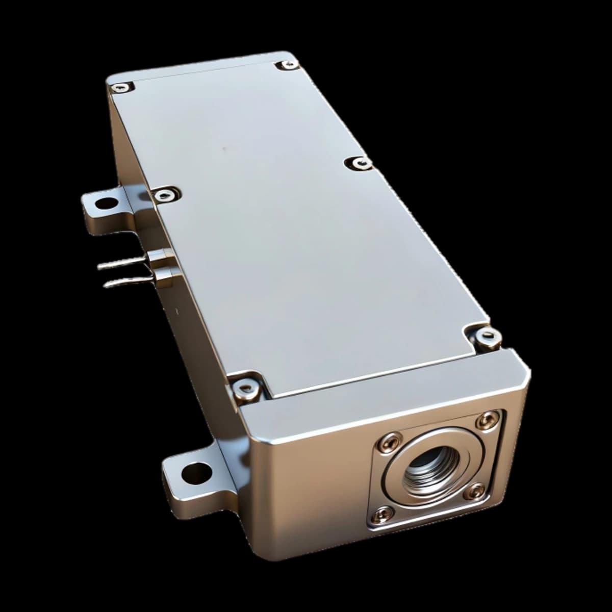
Detailed ER8000 Specifications
The technical material below is retained for this model only. Do not transfer a range, pulse, interface, mechanical or safety value from another 1535 nm product.
Specifications
ER8000 is part of the 1535 nm erbium-glass pulsed laser family. Its current PDF lists pulse energy ≥8 mJ and optical pulse width 13 ns. Repetition-rate status is shown separately in the table. These are the source's distinct specifications; none establishes the distance or accuracy of a finished instrument.
| Parameter | Current PDF value |
|---|---|
| Model | ER8000 |
| Laser Wavelength | 1535nm |
| Laser classification — source entry | Class 1 (classification report and evaluated configuration require confirmation) |
| Pulse energy | ≥8 mJ |
| Laser Pulse width | 13 ns |
| Drive pulse width | ≤ 4 ms |
| Pulse repetition rate | 1~5 Hz |
| Pulse stability | 5 % |
| Raw Beam Diameter | 0.8 mm |
| Beam divergence angle | ≤ 4mrad |
| Beam Mode | TEM00 |
| Operating temperature | -40 ℃ ~ +65 ℃ |
| Storage temperature | -55 ℃ ~+ 75℃ |
| Dimension (mm) | 110×40×24.5mm³ (Three linear dimensions in mm are listed; the source’s mm³ typography is not a calculated volume.) |
| Weight | 220 g |
| Voltage | ≤ 14 V |
| Electric current | 100 A |
| Shock | 1500 G, 0.5 ms |
| Vibration | 20~2000 Hz/20 G |
| Lifetime | >1million shots |
Reading this model's optical specifications
The recorded raw beam diameter is 0.8 mm and divergence is ≤ 4mrad. The current specification table does not state the divergence's full-angle/half-angle convention or the beam-width measurement method. Those definitions remain unspecified until a beam report confirms them. The beam-mode entry does not, by itself, supply a measured M² value.
Values above were checked against the current model PDF, including its inequality signs and stated measurement qualifiers. Source entries of “Class 1” require the corresponding classification report; shock, vibration and lifetime entries likewise need their stated test conditions. Missing tolerances and statistics are not reconstructed from another model or a paper.
Outline dimensions
Open the ER8000 mechanical drawing in its current PDF (page 2)
The PDF identifies this model's 110 mm enclosure. Use its dimensioned mechanical drawing for the correct mounting geometry.
Model-specific conditions and limits
Conditions are retained only when the source states them. They are not reconstructed from a nominal range or wavelength.
Operating conditions
Optical pulse and excitation pulse
ER8000's table gives an optical pulse width of 13 ns and a drive pulse-width entry of ≤ 4 ms. They describe different events: excitation loads energy into the gain assembly, whereas the emitted optical pulse is the short output event. They should not be interchanged when interpreting a trace or specification. This page provides no replacement driver settings; electrical connection and operating procedures belong to the supplied model manual.
Repetition rate, stability and temperature
Repetition-rate table entry: 1~5 Hz. Where a source-version clarification appears above, confirm that individual rating before specifying the ordered configuration. The entry is not a specification for arbitrary bursts or continuous-wave operation. Pulse stability is recorded as 5 %; the current table does not define whether this means RMS variation, peak-to-peak variation or another statistic. A meaningful comparison requires the same pulse count, repetition regime, warm-up state and measurement method.
The recorded operating range is -40 ℃ ~ +65 ℃; storage is -55 ℃ ~+ 75℃. Storage survival and emission performance are separate conditions. Temperature-dependent results should identify where temperature was measured, how the source was mounted and whether it had reached a stable thermal state.
What a useful optical test record contains
Record the model and serial number, output reference plane, wavelength, pulse-energy detector, temporal instrument response, measurement uncertainty and test temperature. Beam testing additionally needs x/y profiles, width definitions and the optical configuration. These details make results comparable without filling absent product specifications with assumed values. ISO 11146-1:2021; ISO 11146-2:2021.
1535 nm Pulsed-Source Integration Context
Technical principle
940 nm pumping: excitation and emission
ERDI's family description identifies a 940 nm pump architecture. This is a family-level statement; the retained ER8000 table does not independently specify its pump diode or wavelength tolerance. Published bulk Er/Yb-glass experiments demonstrate 940 nm pumping with passive Q-switching, establishing a relevant physical example. Their pump powers and measured outputs are not ER8000 specifications. Zou et al., 2017.
The pump supplies excitation to the sensitizer/gain system, while the useful laser emission occurs near 1.5 µm. In an Er/Yb architecture, ytterbium sensitization transfers excitation to erbium. The erbium laser transition supplies the output. Absorbed optical excitation, emitted pulse energy and electrical input are different quantities; their relationship depends on material properties and losses, not on the wavelength names alone. Liu et al., 2003.
Erbium glass: energy storage and optical gain
Erbium-doped glass is the active medium. Co-dopants and host composition influence absorption, transfer processes and available gain. The resonator feeds light through the excited material so that stimulated emission can amplify it. “Erbium glass” is a material class, not a universal composition: a product's glass grade, dopant concentrations and dimensions require its own specification. A paper's material recipe must not be assigned to this model. Liu et al., 2003.
Spinel: the passive Q-switch mechanism
For a configuration using cobalt-doped magnesium aluminate spinel, Co²⁺:MgAl₂O₄ acts as a saturable absorber inside the resonator. Initially it contributes optical loss while excitation accumulates. As intracavity intensity rises, its absorption decreases, enabling a short pulse to develop; the gain then depletes and the absorber recovers. This is passive Q-switching. Undoped transparent spinel and cobalt-doped saturable-absorber spinel are different descriptions. The latter function is well established in Er/Yb-glass literature, but the exact absorber in ER8000 requires confirmation from its own material record. Karlsson et al., 2000.
Output coupler: feedback and extraction
A laser resonator retains part of its circulating light as feedback. The output coupler transmits a fraction as useful emission while reflecting a fraction back into the cavity. Its role differs from a collimating lens or an external protective window. Coupling, gain and internal losses act together; increasing transmission does not universally increase output. Coating values, substrate and cavity geometry belong to the individual design, and are not specified here by analogy with another laser. Karlsson et al., 2000.
Square spots: identify the wavelength and plane
A square profile can refer to pump illumination, an output near-field image or a far-field distribution. These are different observations. A square glass element also does not prove a square intensity pattern. The available model table does not identify a square profile or its plane. Any future product-specific claim should therefore accompany a measured profile, wavelength, distance and x/y dimensions. A general discussion of pump shaping cannot establish the output shape.
Initial divergence and collimation
“Initial divergence” needs a defined position relative to external beam-conditioning optics. Full-angle and half-angle descriptions differ by a factor of two; asymmetric beams also need both transverse directions. Beam-width definitions must accompany the measurement. ISO 11146 supplies methods for widths, divergence and propagation ratios; it does not supply a value for this product. ISO 11146-1:2021; ISO 11146-2:2021.
Collimation changes the wavefront and effective waist. A finite beam still diffracts: in the ideal Gaussian description, a larger waist corresponds to smaller far-field divergence at a fixed wavelength. Real-beam quality and optical aberrations affect the result. This explains why a bare source and an assembled, beam-conditioned optical instrument may have different diameter and divergence entries. Neither “collimated” nor a single spot photograph proves zero divergence. MKS/Newport: Gaussian Beam Optics; MKS/Newport: Focusing and Collimating.
Pulse energy describes emitted energy per pulse; its effect cannot be separated from pulse width, divergence, optical losses, receiver threshold and the stated target/atmosphere conditions. It is not a substitute for a model-specific near- or long-range acceptance test.
Source-stated application context
Application labels indicate evaluation context, not automatic fitness for a finished system.
Applications
OEM distance measurement and optical sensing
ER8000 may be evaluated as a pulsed source for the civilian rangefinding, LiDAR and optical-instrument contexts identified in the product family. Its source energy of ≥8 mJ and repetition range of 1~5 Hz describe the emitter. The completed instrument still needs its own receiver, timing, environmental and measurement validation.
Laboratory characterization and component evaluation
The wavelength and pulse specifications can inform evaluation of optical components and sensing concepts. Compatibility also depends on the required beam profile, temporal response, mechanical envelope and electrical interface. Sharing a wavelength with a communication or medical system does not establish suitability, certification or clinical effectiveness for that application. No such qualification is asserted here.
Confirm short- and long-distance acceptance conditions
- Define minimum distance, target material, reflectance, size and incidence angle.
- Check receiver recovery, optical-axis overlap and strong-return handling at the intended near limit.
- Verify supply tolerance, peak current, grounding, interface levels, connector and timing with the ordered revision.
- For long-distance acceptance, state target geometry, visibility, weather, background and required detection probability.
- Test with the installed window, boresight, field of view, enclosure and thermal path rather than a bare module alone.
- Evaluate accessible emission, labels and failure conditions again for the finished laser product under IEC 60825-1.
Questions to resolve before design release
FAQ
What distinguishes ER8000 from another model in the family?
Its own specification table: for example, ≥8 mJ pulse energy, 13 ns optical pulse width and 1~5 Hz repetition range. Shared physical principles do not make numerical ratings interchangeable.
Does a 940 nm pump mean the output is 940 nm?
No. The pump supplies excitation; the useful erbium-glass laser emission is in the approximately 1.5 µm band. Pump details and output-wavelength tolerances need their respective source records.
Does the family statement identify the exact pump diode?
No. It identifies the described pump band. A specific diode part number, tolerance or qualification must come from the ordered model documentation.
What does the erbium glass do?
It supplies the active gain medium and stores excitation for laser emission. Host composition and co-dopants affect that process; another glass grade cannot be substituted in the description without evidence.
What is the function of cobalt-doped spinel?
In the documented passive-Q-switch architecture it is a saturable absorber: decreasing absorption during pulse build-up helps release stored excitation as a short pulse. The actual absorber in this product needs model-specific confirmation.
Is the output coupler the collimating lens?
No. The coupler provides resonator feedback and partial transmission. External beam-conditioning optics control propagation. A protective window is a further distinct component.
Does a square pump profile guarantee a square output?
No. Identify the wavelength and observation plane for each profile. Neither the pump pattern nor a square package establishes a measured output near field or far field.
What does the listed divergence mean?
The original ER8000 table records ≤ 4mrad. Its full/half-angle convention and width method are not stated, so those definitions require the original PDF or beam report before a direct comparison.
Can collimation remove all divergence?
No. Finite beams diffract. Diameter, beam quality, wavefront and the installed optics determine propagation; verification needs measurements rather than an unqualified collimation claim.
Is pulse energy enough to predict measurement distance?
No. Emitted energy is one source quantity. A completed instrument’s achievable distance depends on its complete optical and receiver system, scene and test conditions. No distance is inferred here.
Does TEM₀₀ give a certified M² or pulse-stability statistic?
No. The mode entry is retained as recorded. Quantitative beam quality requires a propagation measurement, and the stability percentage needs its statistical definition and test record.
Does 1535 nm automatically establish Class 1?
No. A source classification entry needs the report for its evaluated configuration. Where the current PDF table does not specify a class, none is inferred. IEC 60825-1 evaluates accessible emission; wavelength alone does not classify a finished product.
Product evidence and general technical context
The model PDF controls model claims. Public references below explain general engineering principles only.
References
Product and family sources
ER8000 current Technical Downloads PDF — specification pages 1–2, checked on 13 September 2026. The 940 nm pump band is ERDI's family description. Missing tolerances, test methods and internal-material identities require corresponding engineering records. Individual contradictions inside a source document are identified beside the affected values.
Scientific and measurement references
- Zou et al., 2017: Er³⁺,Yb³⁺:glass–Co²⁺:MgAl₂O₄ diffusion bonded passively Q-switched laser, Chinese Physics B 26, 094206. Direct 940 nm-pumped bulk-glass research.
- Karlsson et al., 2000: Diode-pumped Er–Yb:glass laser passively Q switched by use of Co²⁺:MgAl₂O₄ as a saturable absorber, Applied Optics 39, 6188–6192. Absorber and resonator context.
- Liu et al., 2003: Spectra and lasing properties of Er³⁺,Yb³⁺:phosphate glasses, Chinese Optics Letters 1, 37–40. Gain-material context.
- ISO 11146-1:2021; ISO 11146-2:2021: beam-width, divergence and propagation-ratio measurement methods.
- MKS/Newport: Gaussian Beam Optics; MKS/Newport: Focusing and Collimating: propagation and collimation explanations.
- IEC 60825-1:2014: laser-product classification framework.
These references explain physical principles and measurement terminology. Their experimental results are not product specifications or certification evidence for ER8000.
- ERDI ER8000 model PDFModel-specific technical evidence.
- System Design of a Pulsed Laser RangefinderOptical Engineering 30(3), 1991 - link budget, background, noise, detection and range error.
- The Short-Range, High-Accuracy Compact Pulsed Laser Ranging SystemSensors 22(6), 2146, 2022 - pulsed-ToF equation, timing error, reflectivity and temperature effects.
- Laser system range calculations and the Lambert W functionApplied Optics 48(4), B1-B7, 2009 - range performance versus atmospheric transmission, target and system parameters, and threshold SNR; its 1.06 µm example is general context, not ERDI model data.
- Monostatic all-fiber rangefinder systemApplied Optics 54(25), 7687-7694, 2015 - a measured case study of shared-aperture geometry and receiver-recovery loss; it does not establish an ERDI model limit.
- Light Transmission in Fog: The Influence of Wavelength on the Extinction CoefficientApplied Sciences 9(14), 2843, 2019 - measured and modeled wavelength-dependent fog attenuation.
- IEC 60825-1:2014Laser-product classification and accessible-emission requirements; final equipment requires system-level assessment.
- Practical application of pulsed “eye-safe” microchip laser to laser rangefindersOpto-Electronics Review 21(3), 2013 - a peer-reviewed 1535 nm rangefinder implementation; use for general transmitter/receiver and atmospheric-design context, not model specifications.