

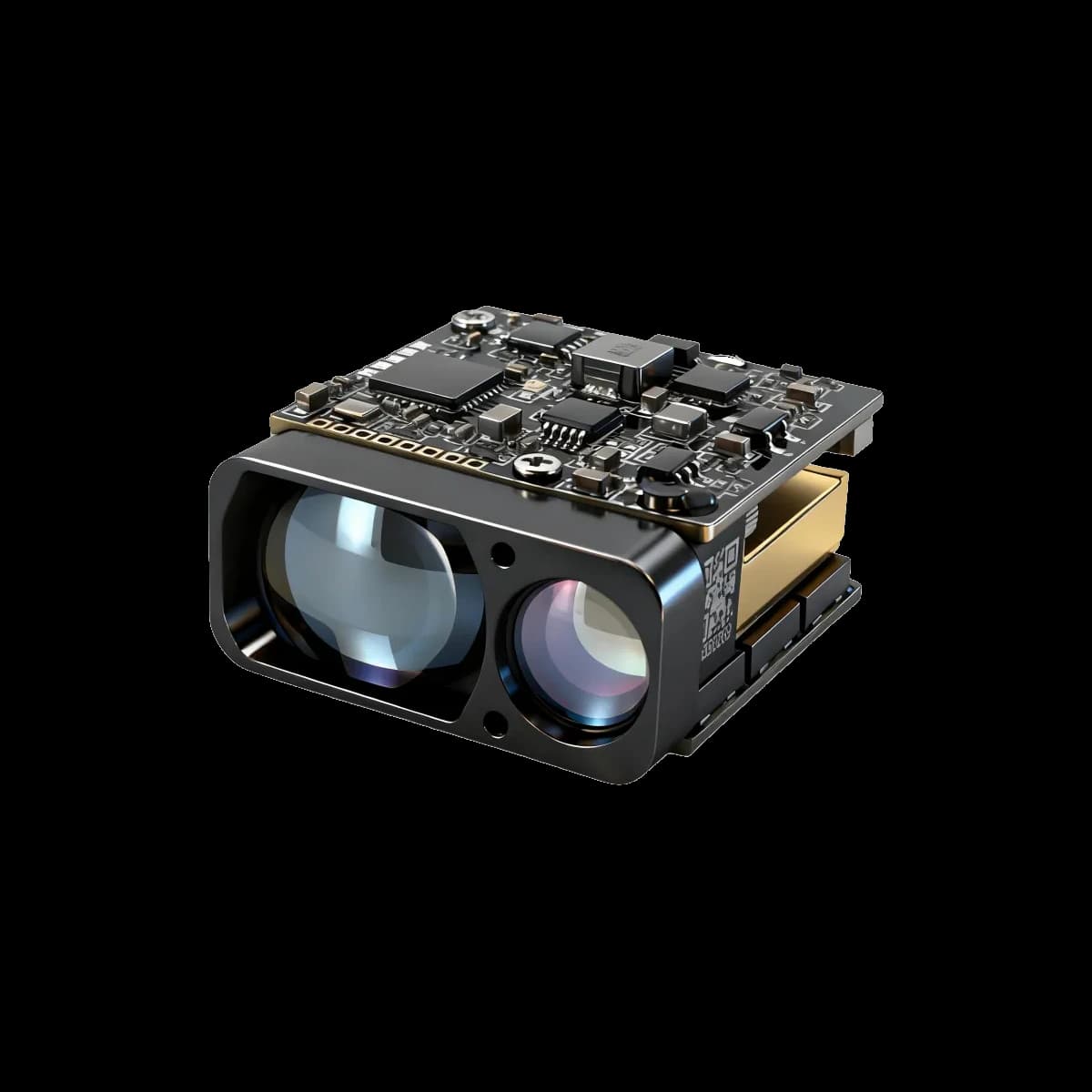
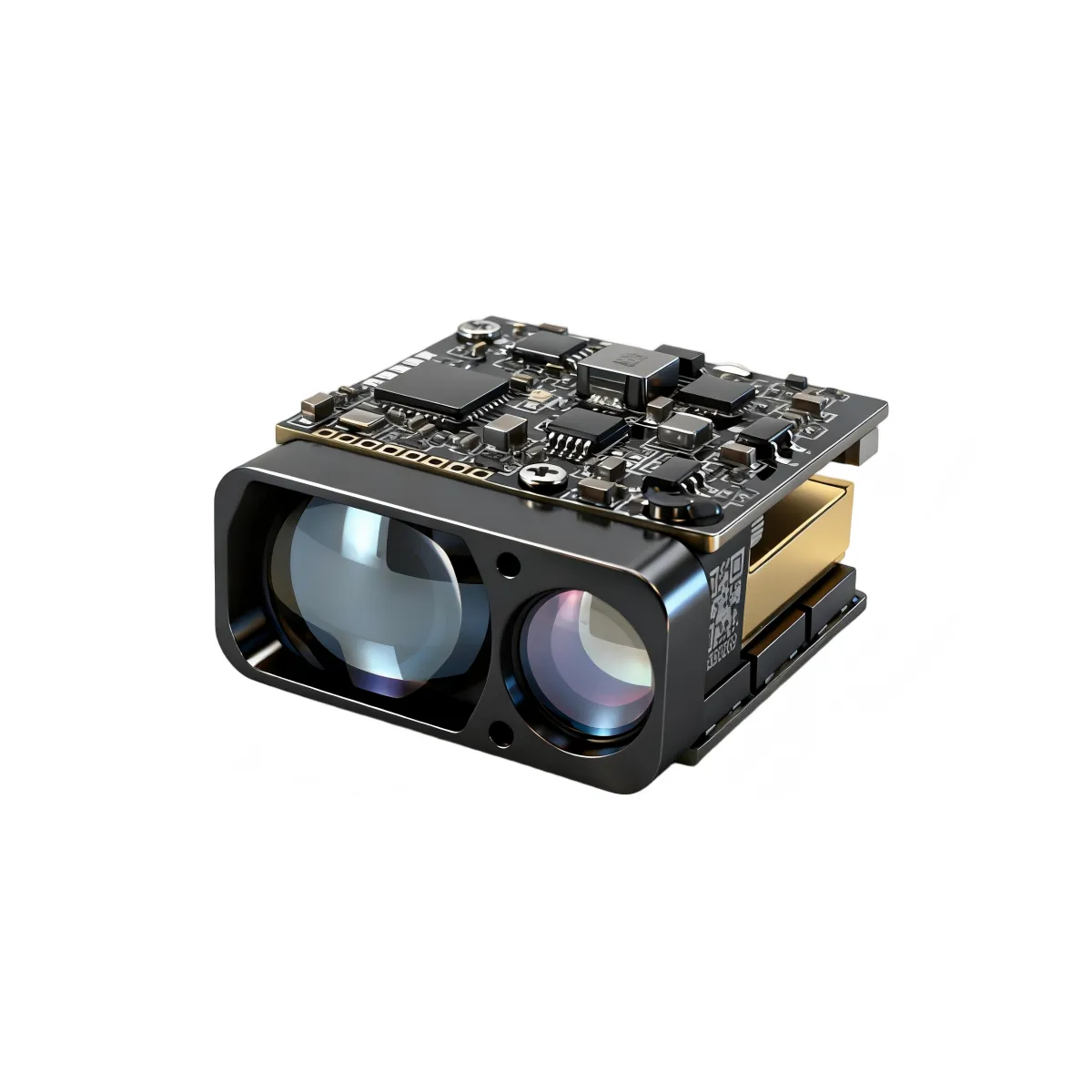
Integrating a laser rangefinder into a UAV gimbal is a system-engineering task. The module must share the payload's optical reference, power budget, timing architecture, thermal path and environmental qualification plan. A compact data sheet is only the starting point; final performance must be verified after the rangefinder, window, cameras, gimbal and flight controller are assembled.
1. Define the ranging requirement
Start with the scene rather than the maximum range printed on a data sheet. Document the minimum and maximum distance, target dimensions and reflectivity, atmospheric visibility, required accuracy, update rate and detection probability. These conditions let suppliers provide comparable test data and help prevent over-sizing the payload.
2. Plan the optical and mechanical layout
- Boresight: Establish a common reference between the rangefinder, visible camera and thermal camera. Provide adjustment and a way to lock the alignment after calibration.
- Clear aperture: Check transmit and receive fields through the payload window at every gimbal angle. Avoid vignetting, internal reflections and coatings with poor 1535 nm transmission.
- Mounting: Use the manufacturer's mechanical drawing and specified locating features. Do not preload or distort the optical housing.
- Balance: Include the module, harness and bracket in the gimbal center-of-gravity calculation before motor sizing.
3. Verify power and communication
Confirm the supply range, peak and average current, startup behavior, grounding and connector definition from the current interface control document. Keep power and signal returns controlled, route noisy motor wiring away from receiver and UART lines, and validate the host command sequence before flight testing.
The LRF0305C product page specifies a 3–5 V supply, operating power below 1.5 W and UART communication at TTL 3.3 V. The host design should still include the transient and margin checks required by the finished payload.
4. Coordinate trigger, timing and data
- Define whether measurements are free-running, commanded or synchronized with an image frame.
- Record trigger-to-result latency and timestamp the returned distance in the same timebase as navigation and imagery.
- Decide how the host handles no-return, multiple-return and out-of-range results.
- Confirm that the selected measurement rate supports platform motion and target-tracking requirements.
5. Provide a thermal and environmental path
Use the module's permitted mounting surfaces and thermal limits from supplier documentation. Analyze heat from the rangefinder together with cameras, processors and gimbal motors. Then qualify the complete payload for its expected temperature, vibration, shock, humidity, sealing and electromagnetic environment. Module-level test data does not replace finished-assembly testing.
6. Calibrate after assembly
- Measure camera-to-rangefinder boresight at a controlled reference distance.
- Check range bias with traceable targets across the intended distance range.
- Repeat alignment after thermal cycling and vibration tests.
- Validate moving-platform latency and stabilization in representative flight conditions.
- Recheck the payload after window, bracket, camera or firmware changes.
LRF0305C example specifications
| Parameter | Published value |
|---|---|
| Wavelength | 1535 nm |
| Specified range | 10–4,000 m |
| Accuracy | ±1 m |
| Measurement rate | 1–10 Hz |
| Supply | 3–5 V DC |
| Operating power | <1.5 W |
| Interface | UART, TTL 3.3 V |
| Dimensions | 27 × 25 × 15.5 mm |
| Mass | 14 g |
Range depends on target and environmental conditions. Eye-safety classification also depends on the complete emitter, optics, divergence and exposure conditions; verify the finished payload against the standards required for its market.
Integration checklist
- Target and visibility conditions defined
- Optical window transmission and clear aperture verified
- Boresight adjustment and calibration procedure documented
- Power, UART timing and error handling tested
- Thermal and center-of-gravity budgets closed
- Environmental and eye-safety tests planned for the complete payload
Product and interface information
Review the LRF0305C product page. For the current mechanical drawing, interface documentation or evaluation support, contact sales@erdicn.com.