

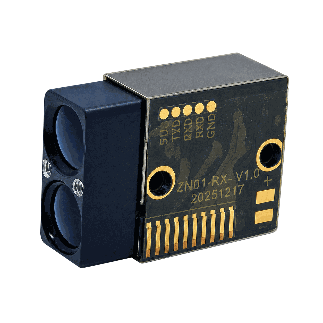
Executive summary. Single-photon time-of-flight (ToF) ranging can make weak optical returns measurable by treating the arrival of an individual detected photon as timing information rather than requiring a large analog return signal. That sensitivity is valuable, but it is not a substitute for optical design, laser-safety assessment, target definition, calibration, or field validation. A useful OEM ranging system combines a pulsed transmitter, a photon-sensitive receiver, accurate timing, signal-processing logic, controlled optics, and a validation plan matched to the real target and environment. The result is not merely a distance number: it is a measured decision input with stated confidence, operating conditions, and integration boundaries.
This article explains where single-photon ranging creates genuine engineering value, how histogram-based direct ToF processing turns sparse photon events into range data, what must be designed around it, and how an OEM team can evaluate a laser rangefinder module or laser distance sensor without turning a laboratory result into an unsupported product claim. It is written for designers of industrial instruments, mobile robots, inspection payloads, intelligent infrastructure, surveying equipment, civilian observation devices, and other legitimate commercial systems that require compact optical distance information.
1. The practical problem: weak returns still carry useful timing information
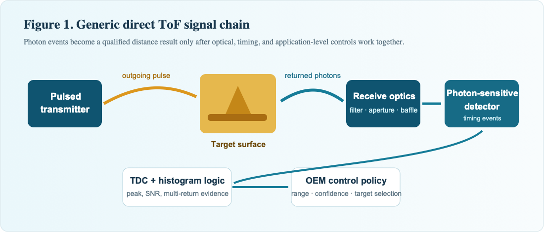
In a pulsed optical ranging system, a transmitter launches a short light pulse and the receiver measures the delay before reflected photons return. For a target at distance R, the basic relationship is:
R = cΔt / 2R: target distance · c: speed of light · Δt: measured round-trip flight time
where c is the speed of light and Δt is the round-trip time of flight. The equation is simple; extracting a reliable Δt from a real scene is not. A useful return can be weakened by range, small target area, low reflectivity, oblique incidence, atmospheric loss, window transmission, transmitter-receiver misalignment, vibration, and competing ambient light. At the same time, the receiver may observe dark counts, electrical interference, afterpulsing, optical crosstalk, or reflections from the host enclosure.
Conventional analog detection can be highly effective when enough return energy is available. A single-photon avalanche diode (SPAD), operated in Geiger mode, takes another approach: an absorbed photon can initiate an avalanche that is converted to a digital event. Repeating a controlled measurement and time-stamping many events produces a statistical record of photon arrival time. A range estimate is then derived from the signal peak in that time record. The advantage is not that physics has removed the link budget; rather, the receiver can make productive use of very small optical signals when the timing, background management, and statistical processing are engineered well.
This distinction matters for responsible product communication. “Single-photon sensitivity” describes the detector architecture’s ability to respond to individual photon events. It does not by itself guarantee a particular range, accuracy, daylight performance, laser class, target-detection probability, or safety classification for an unspecified finished product. Those outcomes remain system-level results.
2. Why single-photon ranging is important for OEM design
2.1 Photon-level sensitivity can extend the useful measurement envelope
At longer distance or on a low-return surface, the number of photons that reach the receiver can become small. A photon-counting receiver can retain timing information in a regime where an analog amplitude measurement may be difficult to use directly. The system may accumulate events over repeated shots and identify a statistically meaningful return peak. This is particularly relevant where the host must balance range against size, mass, average power, thermal budget, or permitted optical output.
The engineering benefit is therefore a larger design space. Instead of assuming that every scene requires a high-energy return, the OEM can consider how aperture, pulse energy, repetition strategy, receiver sensitivity, narrowband filtering, field of view, target class, and integration time work together. That freedom can be useful in compact instruments and mobile platforms, where optical, electrical, thermal, and mechanical resources are all constrained.
2.2 Direct timing makes the measurement traceable
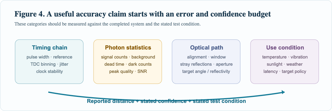
Direct ToF ranging measures a physical delay. The timing chain normally includes a transmit reference, a time-to-digital conversion process, and a calibrated mapping from timing bin to distance. This does not make the measurement automatically accurate, but it gives the design team a clear error budget. Laser-pulse width, transmitter timing reference, detector timing jitter, time-bin width, clock stability, optical-path offset, photon statistics, background counts, and calibration method can each be identified, measured, and improved.
For OEM work, traceability is more useful than a headline number alone. A responsible system specification should identify the target reflectivity, target dimensions, incidence angle, range interval, ambient condition, averaging or update setting, temperature range, mounting condition, and statistical definition behind the stated accuracy or repeatability. If those conditions are not defined, numerical range claims should be treated as incomplete.
2.3 Histograms preserve diagnostic information
Photon arrivals can be placed into time bins referenced to the transmitted pulse. Across repeated shots, a target return appears as a peak above the time-distributed background. A full histogram records the broader timing scene; a partial histogram retains selected local regions around prominent peaks. Both approaches are useful. Full histograms can support development, fault isolation, stray-light investigation, and analysis of unexpected returns. Partial or compressed representations can reduce transfer and memory burden in an embedded design once the measurement behavior is understood.
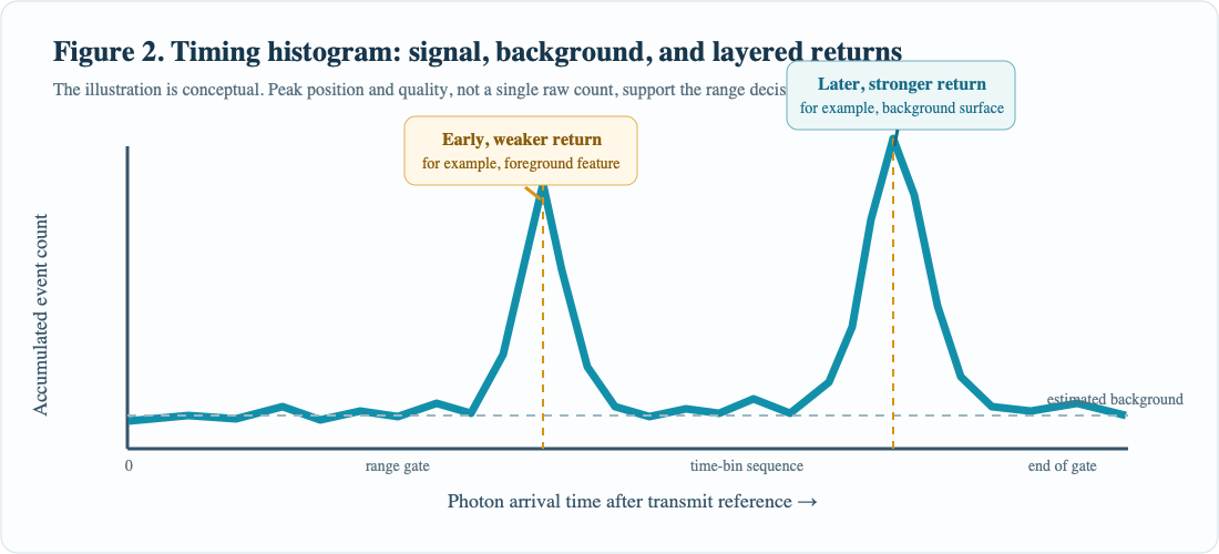
This is a practical advantage over a black-box range output. When an installation behaves differently after a window change, a mechanical revision, a coating substitution, or a change in mounting angle, the timing distribution can help distinguish a real target return from a near-field reflection, background lift, electronic disturbance, or an alignment shift. For production engineering, the ability to inspect evidence can shorten the path from “the range changed” to “this is the physical cause.”
2.4 Multi-return scenes can be handled deliberately
Real scenes are often layered. A thin foreground feature may produce a weak early return while vegetation, a wall, terrain, fog, a window reflection, or another large surface produces a stronger later return. A design that accepts only the strongest early-valid peak can return an answer that is statistically clean but operationally wrong for the application. Histogram analysis permits a system to search for more than one plausible return, report selected returns, or apply a target-selection policy such as nearest, strongest, last, or application-defined.
The correct policy belongs to the host application. Collision avoidance may prioritize the nearest validated obstacle. Terrain following may require a stable ground return. A sighting or inspection system may require the return associated with a selected region of interest. The important point is that multi-return capability is not a cosmetic feature: it connects the receiver architecture to an explicit decision rule. The policy must be tested against representative scenes, including low-reflectance foregrounds and stronger backgrounds.
2.5 CMOS-compatible architectures support compact integration
SPAD arrays and digital timing circuitry can be integrated with substantial on-chip or close-coupled processing. That can support compact receiver modules and a digital interface to the host. For an OEM, compactness is valuable only when it is paired with accessible engineering controls: repeatable power sequencing, stable timing reference, temperature awareness, defined interfaces, electromagnetic compatibility, mechanical datum control, and a test path for optical alignment and calibration.
Integration should not be confused with simplification. A smaller receiver can make the optical system more sensitive to aperture placement, lens choice, detector active-area coverage, baffle geometry, and contamination. The product team should treat the ranging channel as an optical-electronic subsystem, not as a drop-in digital sensor with no optical consequences.
3. From photon events to a distance estimate
3.1 The time-of-flight histogram
A ranging cycle begins with a defined transmit event. The receiver observes photon events over a measurement window and assigns each event to a timing bin. When many cycles are accumulated, uncorrelated background events tend to distribute across the allowed timing interval, while photons associated with a target echo cluster around the corresponding flight time. Signal processing identifies candidate peaks, estimates their timing positions, and evaluates their quality.
Peak quality should not be reduced to peak height alone. Useful checks can include local background estimate, peak width, integrated counts, signal-to-noise ratio (SNR), repeatability across sub-measurements, consistency with a permitted range gate, and agreement with the application’s temporal behavior. An output that includes quality metadata can be more useful than a range value alone, especially where the host must decide whether to display, log, reject, or fuse a measurement.
3.2 Accumulation is a controlled trade-off, not free gain
More laser shots or a longer accumulation interval can improve the statistical separation between a genuine return and random background. In many situations, signal counts rise with repeated measurements while random noise grows more slowly in relative terms. The result can be a clearer peak and a more stable timing estimate. The price is latency, average-power budget, thermal load, and possibly greater susceptibility to motion within the accumulation interval.
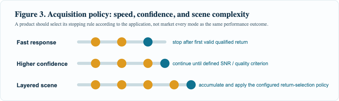
For that reason, a capable architecture should permit a defined trade-off between update rate, energy use, and confidence. A fast mode may stop when it has a valid result. An accuracy-oriented mode may continue until a stronger quality threshold is met. A complex-scene mode may reserve time for resolving more than one peak. None of these modes is universally best. A robot moving quickly through mixed-depth geometry and a fixed industrial gauge observing one cooperative target should not necessarily use the same acquisition policy.
3.3 Coarse-to-fine search can conserve resources
A broad, lower-resolution pilot observation can locate the region where a return is likely to occur. A subsequent acquisition can concentrate timing resolution or processing effort around that region. This type of coarse-to-fine strategy can improve the balance between unambiguous range, precision, memory use, and cycle time. It is also a reminder that “resolution” is not a stand-alone figure of merit. Fine time bins are valuable only when the optical pulse shape, timing jitter, calibration, photon statistics, and target conditions allow the additional information to be used.
4. The advantages of single-photon ranging, stated precisely
Single-photon ranging has substantial advantages when correctly applied. The following claims are useful because they are technical, conditional, and testable:
- High sensitivity to weak returns: individual detected photons can contribute timing information, allowing statistical extraction of a return under low received-photon conditions.
- Efficient use of optical energy: photon-counting approaches can support useful measurements where a design must manage transmitter energy, average power, size, or thermal load.
- Direct distance observability: time-of-flight processing yields a measurement chain that can be calibrated and analyzed from transmit reference to timing peak.
- Multi-echo awareness: timing histograms can expose multiple return candidates rather than forcing every scene into a single amplitude value.
- Configurable speed-confidence balance: shot count, timing window, thresholding, and target-selection logic can be adapted to the application.
- Data-rich commissioning: histograms, peak data, status information, and diagnostic modes can help engineers validate alignment, identify near-field reflections, and investigate field anomalies.
- Compact digital-system potential: SPAD and timing architectures are well suited to modern integrated electronics, which can support compact OEM packages when the full optical and thermal design is controlled.
These advantages do not eliminate the need for sufficient photon-detection probability, appropriate wavelength selection, adequate transmit and receive optics, spectral filtering, background suppression, dead-time management, and valid calibration. A realistic communication program treats them as design opportunities, not as automatic outcomes.
5. Engineering limits that must remain visible
5.1 Ambient light and background photons
Daylight and other sources of background light can increase photon-event rates without carrying target timing information. If background rises, the target peak can become less distinct and the detector can spend more time unavailable after events. A system response may combine narrowband optical filtering, controlled receiver field of view, temporal gating or range windows, optimized pulse-and-shot strategy, background estimation, and selective use of detector elements that have useful SNR. The best solution depends on the optical architecture and the expected scene; it must be validated under representative irradiance, not inferred from an indoor demonstration.
5.2 Dead time, dark counts, afterpulsing, and crosstalk
A SPAD cannot register a new event while it is recovering from a prior avalanche. This recovery interval is called dead time. Thermally generated events can appear as dark counts, and carriers released after a previous avalanche can contribute afterpulses. In arrays, electrical or optical coupling can create crosstalk. These effects are familiar engineering constraints, not reasons to avoid photon counting. They must, however, be included in detector selection, bias control, timing policy, temperature characterization, correction logic, and production screening.
Measured performance should therefore be reported with the background condition and detector operating state. It is not enough to state a bin width or theoretical timing resolution. The operational distribution of range error, valid-measurement rate, false-return rate, and outlier behavior under the intended target and environmental conditions is what the system integrator needs.
σR ≈ (c / 2) · σtIllustrative first-order timing relationship. The final range-error budget also includes calibration, target, optics, background, and algorithm effects.
5.3 Optical alignment is part of the sensor
The receiver does not measure an abstract beam. It measures the return that reaches its active area through the host optics. In coaxial and biaxial layouts alike, the location and shape of the return can vary with distance and target geometry. A bench image from a visible camera is useful, but it is not necessarily the final authority for the photon-sensitive receiver plane. Alignment should be verified using the receiver’s own response where possible, across the intended range interval and mechanical tolerance stack.
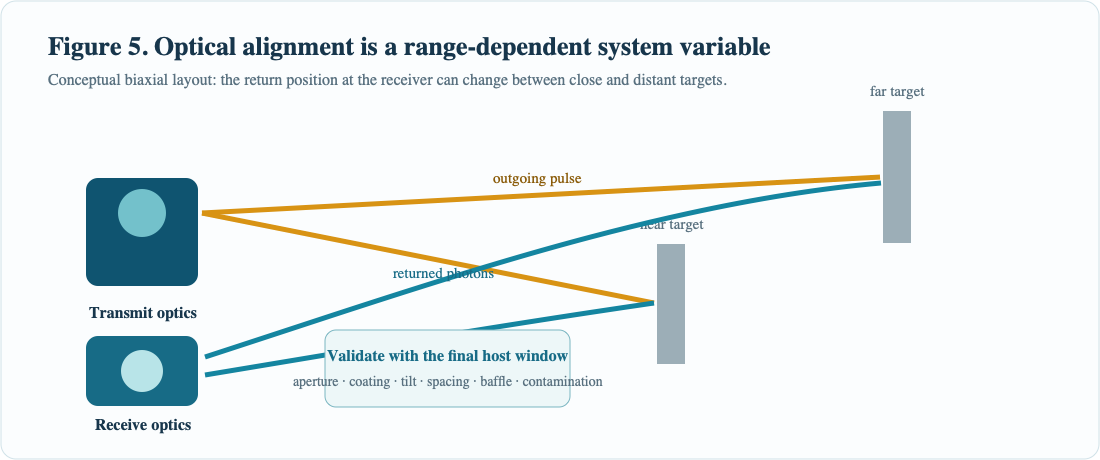
Window material, coating, wedge, thickness, tilt, aperture, spacing, cleanliness, baffles, and internal surface finish can alter transmission and produce unwanted returns. The finished host should be evaluated with its final window and mechanical housing, not only as an open optical bench. If a change is made to the window or enclosure after design verification, the ranging validation should be repeated.
5.4 Temperature and calibration are continuous concerns
Detector behavior, bias conditions, laser output, timing electronics, and mechanical optical alignment can change with temperature. A production-ready design needs a defined temperature measurement and compensation strategy where applicable, as well as controlled distance-offset calibration. Calibration should use stated distances and target conditions. Extremely close targets, highly reflective surfaces, and unrepresentative fixtures can create misleading confidence if they are used as the only calibration reference.
5.5 Laser safety belongs to the completed product
Laser wavelength, pulse width, beam divergence, repetition pattern, accessible aperture, optics, operating modes, fault conditions, and host enclosure all influence the classification of a finished laser product. A component-level statement cannot automatically classify the final instrument. The complete equipment must be evaluated under the applicable laser-safety requirements, including normal operation and reasonably foreseeable fault conditions. Marketing material should never infer safety classification from wavelength alone.
6. An OEM validation plan that produces credible claims
A ranging subsystem should be evaluated with a written test matrix before a headline specification is selected. The following questions provide a practical starting point:
- Target definition: What reflectivity, material, dimensions, texture, and incidence angle represent the application? Are both cooperative and non-cooperative targets required?
- Range definition: What are the minimum, nominal, and maximum working distances? Is there a near-field exclusion zone created by the host optics or mechanical aperture?
- Environmental definition: What sunlight, artificial illumination, fog, rain, dust, aerosol, temperature, vibration, and contamination conditions are relevant?
- Output definition: Does the host need first return, strongest return, last return, multiple returns, or a filtered tracking result? What confidence data must accompany the output?
- Timing definition: What update rate, permitted latency, integration time, motion during acquisition, and synchronization behavior are required?
- Optical definition: What transmitter and receiver apertures, focal lengths, filters, window geometry, baffles, and alignment tolerances are allowed?
- Electrical definition: What power sequencing, interface, clocking, grounding, EMC, and thermal conditions must the host provide?
- Acceptance definition: How will accuracy, repeatability, valid-measurement rate, false-return rate, outlier rate, and recovery after error be measured and documented?
For each test condition, record the configuration, target, distance reference, environmental state, firmware or algorithm revision, raw or summarized timing evidence, selected output, and pass/fail criterion. This information turns a promising demonstration into an engineering record. It also makes future changes auditable: if a new window coating or optical mount changes behavior, the team can compare like with like.
7. Application fit: where photon-counting ToF can add value
Single-photon ToF is most valuable when the application needs distance information from weak or variable optical returns and can benefit from controlled accumulation, timing evidence, or multi-return logic. In industrial automation, it can support distance-aware positioning, material-level observation, and machine-state sensing when the target and environment have been characterized. In mobile robotics, the ability to produce a confidence-aware range measurement can help perception systems decide when to fuse, reject, or request another observation. In civil UAV and inspection payloads, compact optical ranging can complement imaging or stabilization functions, subject to payload, vibration, weather, and laser-safety evaluation.
In intelligent transportation and infrastructure, a ranging channel may help measure clearance, approach distance, or object position, but it must be validated for the scene dynamics, target mix, sunlight, precipitation, and fail-safe behavior relevant to the intended function. In surveying and mapping, a distance channel can provide useful embedded information; it should not be called survey-grade unless the complete instrument, reference chain, calibration method, and field procedure support that claim. In handheld or observation equipment, photon-sensitive ranging may help preserve a compact optical envelope, but the completed product still needs robust alignment, window control, user-interface logic, and safety evaluation.
These are application directions, not pre-approved specifications. The correct question is never simply “Can it range?” The better question is “Can the complete host provide a valid range result, at the required confidence and update rate, for the defined target and environment?”
For search and product-selection purposes, this discussion is relevant to the following OEM terms: single-photon LiDAR, photon-counting LiDAR, direct ToF LiDAR sensor, laser rangefinder module, laser ranging module, laser distance sensor, long-range distance measurement, multi-return laser ranging, industrial LiDAR sensor, robotics distance sensor, and OEM optical ranging module. Whether an OEM is evaluating a 905 nm laser rangefinder module, another wavelength architecture, or a custom optical ranging design, the final choice must follow the controlled model data and complete-system validation.
8. A responsible path from concept to a production system
ERDI works with OEM teams on the system questions that determine whether a ranging concept becomes a repeatable product. Early engineering discussion should include the intended wavelength architecture, maximum and minimum range, target reflectivity, host optics, window construction, interface, update-rate requirement, operating environment, available power, mechanical envelope, qualification expectations, and project volume. That information is more valuable than a request for a generic “maximum range,” because it allows the design to be evaluated against the application rather than against an undefined ideal target.
A disciplined development sequence is usually more efficient than trying to optimize every parameter at once:
- Define the target and acceptance conditions.
- Establish the optical and timing architecture.
- Build an early measurement chain with diagnostic evidence available.
- Align and calibrate with controlled targets and reference distances.
- Characterize background light, temperature, vibration, window, and enclosure effects.
- Select the acquisition and target-return policy that matches the use case.
- Repeat the validation on production-intent hardware.
- Complete final product safety, compliance, and reliability assessments.
This approach keeps technical promotional language aligned with evidence. It lets an OEM explain why a photon-sensitive ToF architecture is relevant to its design while retaining the distinction between general technology, component behavior, and verified performance of the finished system.
9. Conclusion
Single-photon time-of-flight ranging is compelling because it converts sparse optical returns into usable timing information. Its advantages include high sensitivity, direct timing observability, histogram-based diagnostics, configurable speed-confidence trade-offs, and the ability to treat multi-return scenes as an engineering problem rather than an exception. The technology is strongest when it is paired with realistic link-budget thinking, controlled optics, background management, thermal and bias control, target-aware signal processing, calibration, and final-system validation.
For an OEM, the objective is not a generic claim of maximum distance. It is a defendable range measurement for a specified target, in a specified host, under specified environmental conditions. That is the standard by which a photon-counting ranging subsystem should be selected, integrated, and communicated.
Technical inquiry: For an engineering review of a laser rangefinder module, laser distance sensor, or OEM LiDAR ranging solution, provide the target material and reflectivity, minimum and maximum distance, target size and angle, operating environment, host-window details, required update rate, interface, mechanical envelope, quantity, and project schedule. ERDI can then assess the appropriate ranging architecture and validation path for the intended civilian application.
References
- F. Piron, D. Morrison, M. R. Yuce, and J.-M. Redouté, “A Review of Single-Photon Avalanche Diode Time-of-Flight Imaging Sensor Arrays,” IEEE Sensors Journal, 21(11), 12654–12666, 2021. https://doi.org/10.1109/JSEN.2020.3039362.
- J. S. Massa, G. S. Buller, A. C. Walker, S. Cova, M. Umasuthan, and A. M. Wallace, “Time-of-Flight Optical Ranging System Based on Time-Correlated Single-Photon Counting,” Applied Optics, 37(31), 7298–7305, 1998. https://doi.org/10.1364/AO.37.007298.
- F. Z. et al., “Development Status and Trends of Single-Photon LiDAR Technology,” Opto-Electronic Engineering, 2024. https://doi.org/10.12086/oee.2024.240037.
- N. R. Newbury, I. Coddington, and W. C. Swann, “Precision Ranging LIDAR Using Femtosecond Fiber Lasers,” National Institute of Standards and Technology, 2009. NIST publication.
- International Electrotechnical Commission, IEC 60825-1: Safety of Laser Products — Part 1: Equipment Classification and Requirements. Consult the current applicable edition and national implementation for final-product assessment. IEC Webstore.
Editorial note: This article describes general single-photon time-of-flight engineering principles. It does not disclose confidential implementation details or constitute a specification, certification, safety classification, or performance guarantee for any component or completed product. Product selection and final claims must be based on the applicable controlled data and validation of the complete host system.
ERDI official website: https://erdicn.com