Multifunction rangefinder

This multifunctional rangefinder belongs to the field of optical instruments for measuring distance, and there are more and more modern instruments for measuring distance, some of which have high measurement accuracy and advanced technology. For example, laser, radar, photoelectric and other measurements are very modern means, but the price of such equipment is high and it is not easy to maintain well. It's not always easy to use; Although some structures are not complex, their measurement functions seem to be insufficient, and the scope of application is not wide enough.
The purpose of this multifunctional rangefinder is to design a rangefinder with simple structure, convenient reading and calculation, which can be used not only for long-distance horizontal distance measurement, but also for periscope distance measurement, amplification distance measurement and object height measurement
The multifunctional rangefinder achieves its purpose in the following way: The principle is to use the geometric relationship between the height on the hypotenuse of a right triangle and the hypotenuse, the base line on the instrument as the height on the hypotenuse, and a line obtained on the rangefinder after measurement as a line drawn by the height on the hypotenuse. In this way, the length of another line on the hypotenuse is calculated - that is, the distance between the rangefinder and the measured object, that is, the object distance.
The specific structure is: first, the position and length of the baseline are determined on the bottom plate; The measuring telescope is fixed on the short side of the right Angle branch, and the right Angle bracket can be rotated around the pin shaft. The upper edge line of the long side of the right Angle bracket coincides with the base line of the instrument, and the long side has a chute near the tail. The sighting telescope is installed on a slide seat fixed on the bottom plate and can slide along the slide rail. The end of the objective lens is vertically connected with a horizontal periscope. The micrometer is installed on the lower part of the bottom plate, and its axis intersects vertically with the base line of the instrument on the projection and is parallel to the axis of the measuring telescope and the sighting telescope when not working. There is an annular groove on the differential cylinder of the micrometer, which is inlaid with a slip ring with a protruding small cylinder. The calibration sleeve is fixed on the base plate, and the zero line is in the same vertical plane with the base line.
The rangefinder also has two round simple periscopes and one elevation periscope as accessories of the machine.
The multifunctional rangefinder structure and use are very simple, as long as according to the reading of the dial meter can be immediately found from the meter to detect the distance of the measured object from the rangefinder, but also can easily measure the elevation Angle and height of the object, but also can scope ranging, amplification ranging, very convenient to use.
The utility model is further explained by the following embodiments in combination with the attached drawings:
Figure 1 is the front view of the rangefinder.

Figure 2 is a top view of the rangefinder.
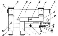
Figure 3 is a diagram of the right Angle bracket.

Figure 4 is a diagram of the annular slot on the differential of the micrometer.

Figure 5 is a schematic diagram of a slip ring with a small cylinder protruding from the outer square and the inner circle.

Figure 6 is a schematic of a cylindrical periscope.

Figure 7 is a schematic of the elevation measuring periscope.

First of all, design the position and length of base line AB as required · Then pass the pin 12 through point A to install the right Angle bracket 9 on the bottom plate 1, and make the upper edge line of the long side of the right Angle bracket 9 coincide with line AB, so that the zero line of the scale sleeve 22 in the micrometer 6 falls directly below B, as shown in Figure 2. This zero line at this time coincides with the base line AB. The measuring telescope 11 is mounted on the short side of the right Angle bracket 9 through support 17) the auxiliary line is parallel to the axis of the sighting telescope 10 on the slide holder 14 supported by support 18 and the micrometer 6. The position of the sighting telescope 10 on the slide holder 14 can be changed by moving the handle 2. In order to adapt the distance of the two telescopes to the different eye distances of different people, 5 is a horizontal periscope placed on support 15; annular groove 25 is provided on the differential cylinder of the micrometer 6; a slip ring with a protruding cylinder 20 is inlaid; a slip ring with a protruding cylinder 20 can be translated in the slide 24 with the axial movement of the differential cylinder; when the object is measured, First aim the aiming telescope 10 at the measured object, and then rotate the knob of the micrometer 6. 7) With the rotation and axial displacement of the differential cylinder, the slip ring 23 and the protruding cylinder 20 begin to move outwards. Thus, it drives the long side of the right Angle bracket 9 to rotate clockwise. · When it turns to the object being measured from the measuring telescope 11, it stops rotating the knob 7 and screws 8 that pass through the slot 31 on the long side of the right Angle bracket 9. · At this time, the axial moving distance of the differential cylinder can be read from the micrometer. A and B can be regarded as the height on the hypotenuse of a right triangle (that is, the base line length), and the axial movement distance of the micro-dividing cylinder is regarded as a section marked by the height on the hypotenuse of a right triangle, then the other section divided by the height on the hypotenuse of a right triangle -- the object distance can be calculated. In advance, you can calculate a list of the axial movement distance of each different differential cylinder and its corresponding object distance, and you can immediately find out when you need to use the figure 3 and 13 are two cylindrical periscopes, their length can be the same or different, when the need for periscopes, They can be vertically inserted into the support in front of the port of the measuring telescope 11 and the horizontal periscope 5. The port of the cylindrical periscope 3 and 13 are communicated with the port of the horizontal periscope 5 and the measuring telescope 11, respectively, and the object distance reflected from the cylindrical periscope can be measured. The periscope 3 and 1 3 are placed horizontally on the support 4 and 21, and the end is connected to the mirror port of the horizontal periscope 5 or the measuring telescope 11, and the end is on the outside, then the distance of the object to be measured farther away can be measured. When calculating the distance of the object, the number detected by the above method must be increased by a certain multiple, the size of the multiple depends on the length of the circular simple periscope. When the length of each circular periscope is twice that of the baseline, and the two circular periscopes are lowered horizontally on both sides for magnification and ranging, the number found by the above ranging method should be multiplied by 5 times to obtain the actual object distance. It is also possible to add only a cylindrical periscope on one side for magnification and measuring distance. The accessory elevation periscope can be vertically inserted into the support used by support 21 and the original cylindrical periscope 3, so that the entire elevation periscope is directly in front of the aperture of the measuring telescope 11 and horizontal periscope 5. The reflector 26 is at an Angle of 45° from the horizontal plane. The light reflected from the upper reflector 27 to the reflector 26 can be seen directly from the telescope; Reflector 27 can rotate a certain Angle around the supporting point of the mirror29. · For height or elevation measurement, align the periscope with the direction of the measured object, rotate the reflector 27 to a certain Angle, and the measured object will be reflected into the two telescopes 11 and 10, and the Angle of rotation of the reflector 27 is indicated by the pointer 30. The value can be read out on the scale plate 28. · The elevation Angle and height of the measured object can be calculated according to the degree of the Angle and the axial travel distance of the differential. The whole rangefinder is connected to the top plate 16 of the tripod support through the bottom plate 1.