ERDI TECH LTD's Innovative Laser Rangefinder Receiver Circuit

This technology pertains to advancements in laser rangefinding devices, specifically, a novel laser rangefinder receiver circuit. Traditional laser rangefinders primarily utilize a photosensitive element to receive laser signals reflected by a target, converting them into electronic signals.

ERDI TECH LTD's primary objective is to introduce a laser rangefinder receiver circuit thatboosts the sensitivity of received laser signals. Our innovative approach integrates:
-
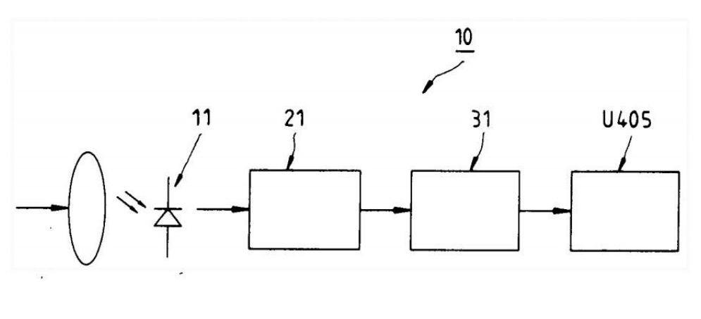
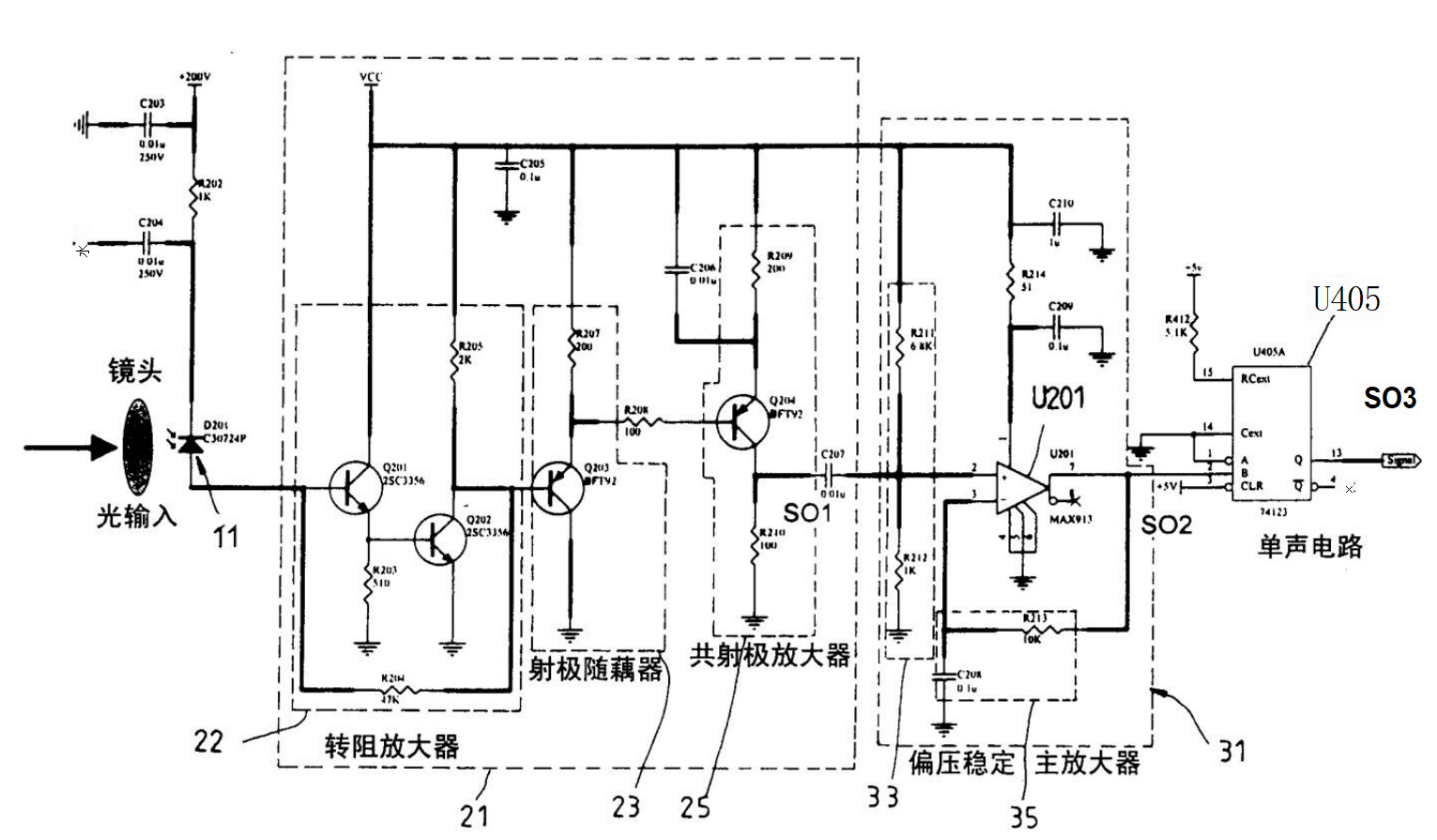
A Photosensitive Element: Converting incident light signals into current signals. In this advanced design, we employ an Avalanche Photo-Detector (APD) that, when exposed to reflected laser signals, biases into reverse voltage, generating an internal gain of 100 and outputting a current signal.
-
Transimpedance Amplification Stage: This stage, upon connection to the photosensitive element, transforms the current signal from the photosensitive element into a voltage signal. It comprises a transimpedance amplifier formed by transistors Q201 and Q202, resistors R203 and R205. An emitter follower coupler connected to this amplifier comprises transistors Q203 and resistors R207. A common emitter amplifier, consisting of transistor Q204 and resistors R209 and R210, is then linked to this coupler for signal transmission to the main amplification stage.
-
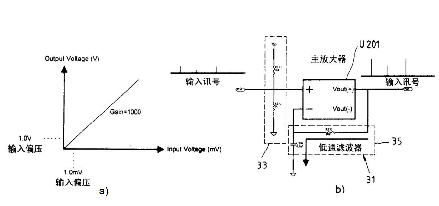
Main Amplification Stage: Connected to the transimpedance amplification stage, this segment amplifies the voltage signal. It incorporates a main amplifier, U201, alongside several resistors and capacitors. The main amplifier receives stable biasing from a bias stabilization circuit, formed by resistors R211 and R212. An output low-pass filter, composed of resistor R213 and capacitor C208, adjusts the DC bias at the input of the main amplifier for stability against temperature variations.
-
Click Circuitry: In our embodiment, an integrated circuit (IC) connects to the main amplification stage, reshaping the amplified voltage signal into digital pulse trains with predetermined widths. As depicted in Figure 3, even with a gain of 1000 for the main amplifier U201 and 1mV input DC bias drift leading to a 1V output change, our stable bias supply ensures no malfunctioning in the click circuitry. This prevents erroneous operations caused by voltage fluctuations.
By leveraging this circuit architecture, ERDI TECH LTD's design converts reflected laser signals into electronic signals, amplifying and conditioning them with high magnification and minimal susceptibility to voltage drifts. This enhanced sensitivity facilitates accurate distance measurements by laser rangefinders.
In practical implementation, our innovation is fitted within laser rangefinders, interfacing seamlessly with their circuitry. The processed signals from our circuit can then be utilized by the rangefinder's computational circuits to ascertain target distances.
In conclusion, ERDI TECH LTD's laser rangefinder receiver circuit offers superior signal amplification and conditioning with minimized voltage instability, thereby elevating the sensitivity of laser distance measurements. This advancement exemplifies our commitment to innovative technology solutions that enhance performance and reliability in practical applications. For more insights on laser rangefinder technology, visit our website at www.erdicn.com.