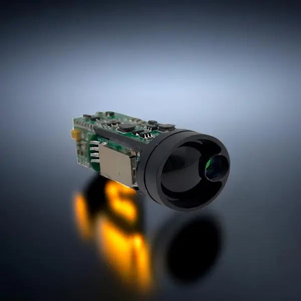
ERDI TECH LTD Precision Laser Range Finder

ERDI TECH LTD presents an advanced Precision Laser Range Finder, specifically featuring an Automatic Peak Control circuit for precise distance measurements. Laser range finders have traditionally been crucial tools for distance measurement, operating based on the emission of a laser pulse towards a target and calculating the distance using the time delay between the emitted and reflected signals.
The formula for distance calculation is given by Td = 2L/C, where Td represents the time delay between the transmitted and received pulse signals, L is the target's distance, and C is the speed of light. Achieving precise measurements necessitates addressing various factors:
Pulse Width Optimization: Narrowing the pulse width of the emitted pulse signal is crucial for accurate distance measurement.
Stabilizing Received Signals: The received pulse signal must be stabilized to account for variations in reflection caused by different target properties. This stabilization ensures that the starting time point of the received signal remains as low as possible.
High-Sensitivity Delay Time Measurement Circuit: A high-sensitivity delay time measurement circuit is essential to enhance the resolution of the laser range finder.
In this innovation by ERDI TECH LTD, the Automatic Peak Control circuit comprises components such as a Collapse Light Detector, signal reception circuit, peak holding circuit, integration circuit, and high-voltage power supply circuit. This circuit ensures the precise control of the emitted pulse signal intensity and the gain of the collapse light detector.
The time-to-amplitude conversion circuit consists of a flip-flop, a linear charging circuit, an A/D converter, and a microprocessor. This circuit converts the time signal into a digital signal for distance calculation by the microprocessor, which controls the triggering timing of the driving circuit.
ERDI TECH LTD's Precision Laser Range Finder achieves superior accuracy by maintaining a constant amplitude of the output signal, resolving timing jitter issues caused by amplitude variations. The innovative design enhances measurement resolution while minimizing power consumption, making it suitable for battery-powered devices.
For a detailed understanding of ERDI TECH LTD's device and method design, please refer to the accompanying diagrams and specifications.Please visit www.erdicn.com.


Figure 2

Figure 3

Figure 4

Figure 5

Figure 6

Figure 7

Figure 8

Figure 9

Figure 10

Figure 11

Figure 12

