

Meet the LR1000E2
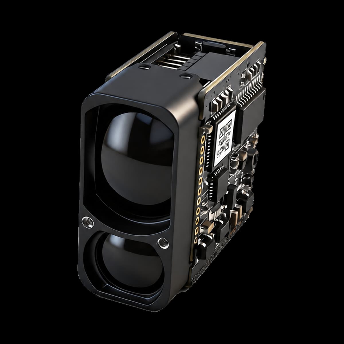
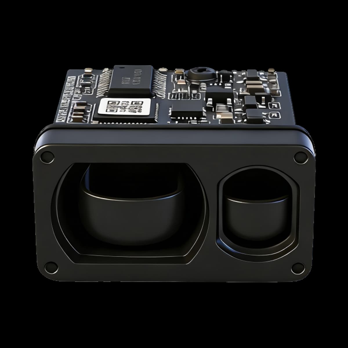
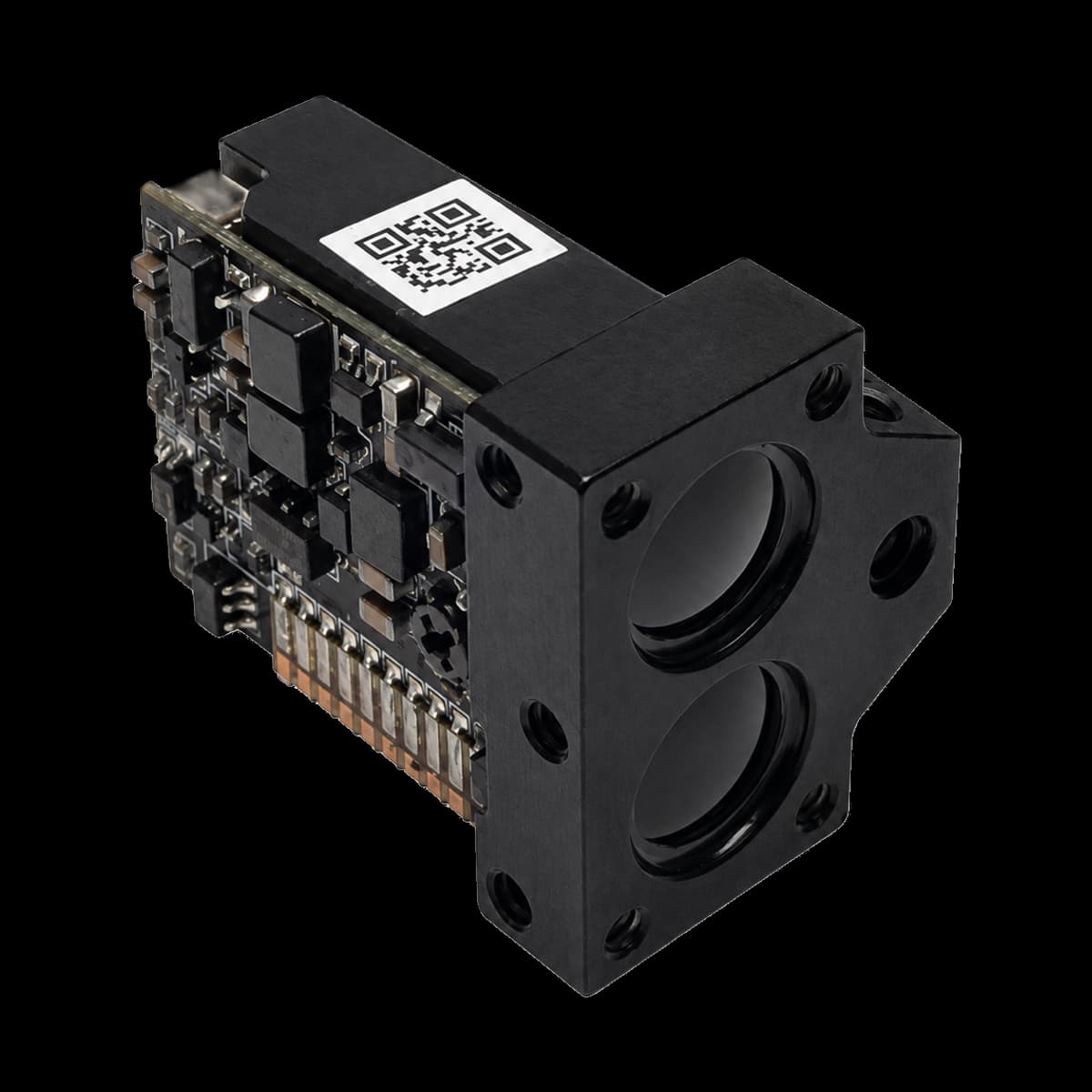
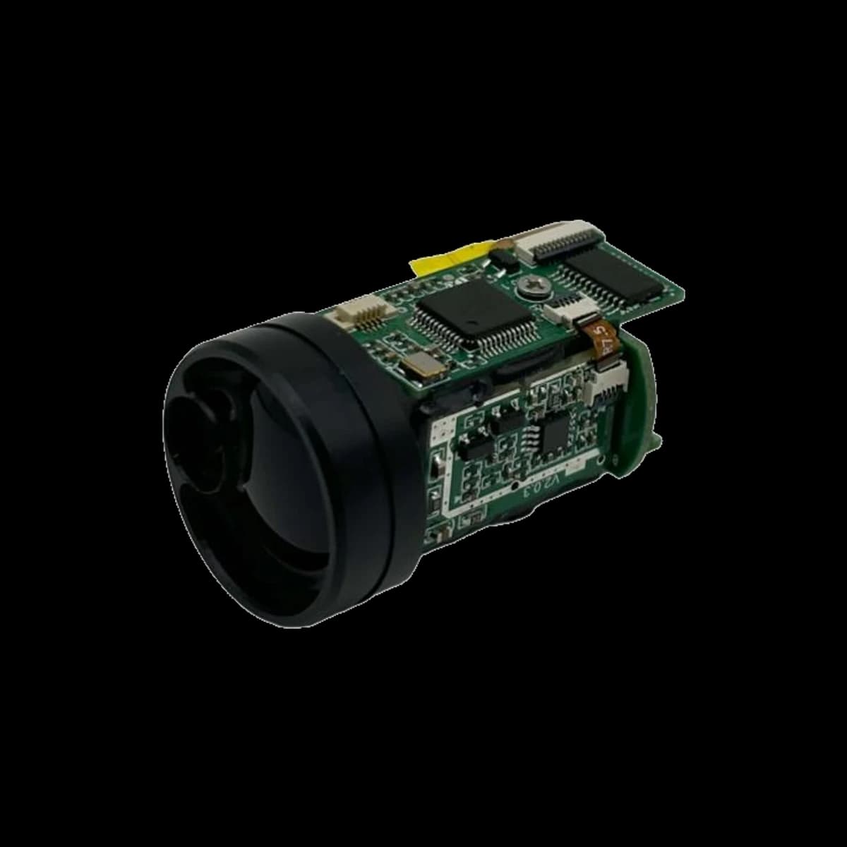
The LR1000E2 is a compact ranging module in the E2 mechanical format. It provides digital distance measurements for equipment that needs a ranging subsystem rather than a standalone handheld meter.
Its standard measurement range is 4–1000 m. Accuracy is specified in two distance intervals, with a distance-dependent term above 400 m. Use the model-specific accuracy formula when setting your system requirements.
The UART-TTL interface supports host-controlled measurements. The manual includes test-software guidance, a six-pin interface definition, and a hexadecimal communication protocol. Use the E2 drawing for packaging and mounting.
1000 m range class
4–1000 m standard range with a model-specific long-distance accuracy formula.
Host-controlled ranging
3–10 Hz (adaptive); single-shot and continuous measurement modes.
Compact integration
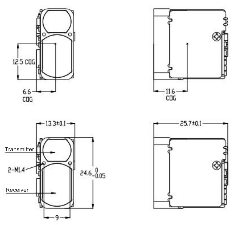
25.7 × 13.3 × 24.6 mm nominal dimensions in the current mechanical drawing; detailed tolerances remain controlling.
UART-TTL interface
115200 bps communication and a 3.3–5 V supply range; use the model-specific pinout and command table.
LR1000E2 Specifications
Read performance values with their target and test conditions. The linked user manual provides the complete mechanical, electrical, and communication details.
| Parameter | Value | Conditions / notes |
|---|---|---|
| Laser wavelength | 905 ± 5 nm | — |
| Measurement range | 4–1000 m | Standard range; actual reach depends on target and environment. |
| Ranging accuracy | ±1 m (D ≤ 400 m); ±(1 + 0.001D) m (D > 400 m) | Whiteboard target, 90% reflectivity: 2.3 × 2.3 m for the first distance interval; 2.3 × 4.6 m for the second. |
| Measurement update rate | 3–10 Hz (adaptive) | Completed distance outputs; not the optical pulse-repetition rate. |
| Communication interface | UART-TTL | Custom configurations are specified separately. |
| Baud rate | 115200 bps | — |
| Supply voltage | 3.3–5 V | — |
| Operating temperature | −20 °C to +55 °C | — |
| Storage temperature | −40 °C to +60 °C | — |
| Mechanical drawing dimensions | 25.7 × 13.3 × 24.6 mm | Drawing nominal values. Observe the individual tolerances in the model drawing; do not machine from the rounded summary alone. |
| Weight | ≤10 g | — |
| Ingress protection | IP67 | Lens cavity only; not a blanket rating for the exposed board or the complete host product. |
| Laser safety class | Class 1 | As stated in the model manual; finished-equipment assessment is separate. |
| Laser beam divergence | < 9 mrad | — |
| Optical material | Resin Aspheric Lens | — |
| Receiver aperture | 9.2 mm × 14.5 mm | — |
| Startup time | ≤ 200 ms | — |
| Inrush current | < 350 mA | — |
| Sleep power consumption | < 1 mW | — |
| Standby power consumption | < 0.3 W | — |
| Short-range power consumption | < 0.6 W | — |
| Operating power consumption | ≤ 1 W | — |
- For civilian equipment only. The model manual prohibits military applications.
Operation and Data Output
Single-shot mode requests one reported distance. For a weak return, the manual describes repeated internal measurements before reporting stable distance data. Continuous mode produces repeated results at the documented adaptive update rate.
The standard measurement-rate specification is 3–10 Hz (adaptive). Use the current protocol table for command timing and output format.
Electrical Interface
| Pin | Signal | Function |
|---|---|---|
| 1 | GND | Power ground |
| 2 | VCC | Power input |
| 3 | I/O (Reserved) | Reserved for expansion |
| 4 | TXD | Transmit data: module → host |
| 5 | RXD | Receive data: host → module |
| 6 | SW-SHOT | Function-enable input. The required control polarity must match the supplied configuration. |
Mechanical Dimensions
Use the drawing and its tolerances for installation. This drawing is reproduced directly from the current LR1000E2 user manual.
905 nm Pulsed Time of Flight and APD Reception
The following explains the general measurement principle of a 905 nm pulsed ranging system with APD reception. A short near-infrared pulse travels to the target, and reflected light returns through the receiving optics to a silicon avalanche photodiode (APD). The receiver converts the optical return into an electrical signal for distance measurement. Individual circuit implementations and performance remain model-specific.
Transmit pulse → target → reflected light
Receiving optics → APD → timing processing → host
A 1 m change in distance corresponds to about 6.67 ns of round-trip travel time in free space. This is a physical relationship, not a claim about the module’s timing resolution or measurement accuracy. [1]
Why an APD helps detect a weak return
A silicon APD provides internal avalanche gain before subsequent signal processing. This can help a receiver detect weak optical pulses, but the gain also brings excess noise. More gain is not always better: receiver bandwidth, background light, bias stability, and temperature all affect the usable signal-to-noise ratio. [2] [3] [8]
Why range depends on the target
A large, bright surface usually returns more usable light than a small, dark, or angled one. At long distances, beam spreading can place only part of the transmitted light on the intended target. The receiver also sees losses through the atmosphere and any protective window, so a maximum range rating must be read with its target conditions. [1] [4] [7]
Why wavelength stability and filtering work together
Narrowband optical filtering reduces unwanted background light while passing the laser return. Lower transmitter wavelength drift helps preserve this overlap as temperature changes. Filter bandwidth, incidence angle, component variation, and temperature must still be considered together; a narrow filter alone does not establish sunlight immunity. [5] [6] [7]
Why timing errors become distance errors
Noise changes the estimated arrival time of a return pulse. A fixed-threshold detector can also trigger at different times as pulse amplitude changes, an effect called timing walk. The complete receiver and timing chain determines the final measurement error—not the detector response time by itself. [1] [8] [12]
Choose by Target, Range, and Integration
The E2 and E4 families cover 1000, 1200, 1500, and 2000 m nominal range classes. LRF1200A1 and LRF3000A1 have their own electrical, mechanical, and measurement specifications. Equal range-class numbers do not make different families pin-compatible or mechanically interchangeable.
Start with the smallest and darkest target your application must measure, the required update rate, and the available installation space. Then compare the model-specific supply, interface, drawing, and long-range accuracy formula. Do not select only by the maximum range number.
Integration Applications
- Handheld observation and ranging instruments
- Night-vision and thermal-imaging equipment with distance readout
- Telescopes and outdoor ranging instruments
Validate the complete installation with representative targets, lighting, temperature, and the final protective window.
From Bench Test to Installed System
- Power and signals: size the supply for transient current, use a common signal ground, and match logic levels. A module’s supply-voltage range is not automatically the voltage tolerance of its UART pins.
- Optical window: choose material and coatings with suitable transmission near 905 nm. Keep transmit-to-receive reflections low, avoid aperture clipping, and test the assembled window for false near returns.
- Target: test dark, small, angled, wet, and partially obscured surfaces at the required distance rather than only a large white panel.
- Environment: assess direct sunlight, visibility, condensation, dust, and temperature changes. Keep the optical surfaces clean.
- Data handling: use the model manual for byte order, scaling, checksum, and command timing. Check the STA/status field before interpreting the distance bytes, and reject failed measurements according to the model protocol.
- Laser safety: assess the finished equipment, including added optics, controls, access, labeling, and applicable operating conditions. A component rating alone does not establish the system’s laser class.
LR1000E2: Frequently Asked Questions
What range should I use when selecting LR1000E2?
Use 4–1000 m as the standard measurement range, and evaluate it against the target you actually need to measure. A nominal maximum range is not an all-target guarantee.
How should I read the LR1000E2 accuracy formula?
±1 m (D ≤ 400 m); ±(1 + 0.001D) m (D > 400 m). D is the measured distance in meters. Whiteboard target, 90% reflectivity: 2.3 × 2.3 m for the first distance interval; 2.3 × 4.6 m for the second. At 1000 m, the long-distance formula evaluates to ±2 m.
Is LR1000E2 mechanically interchangeable with the corresponding E4 model?
No interchangeability should be assumed from a shared range class. The E2 drawing shows 25.7 × 13.3 × 24.6 mm nominal dimensions. Compare overall envelope, mounting details, optical alignment, connector position, and tolerances before reusing an installation.
Can I connect the UART pins directly to RS-232 or RS-485?
No. UART-TTL refers to logic-level signals, not the electrical signaling of RS-232 or RS-485. Use an appropriate interface converter where required and confirm the ordered module’s signal levels. The supply-voltage range is not a specification for the UART input-voltage tolerance.
Why can a white wall be measured farther away than a dark or small object?
Distance depends on the strength of the accepted return. Reflectance, illuminated target area, viewing angle, and beam spreading all matter. A dark object can absorb more of the pulse, while a small object may intercept only part of the beam. A range quoted for a large white target or building is not a guarantee for clothing, vegetation, wires, or other small targets. [4]
Can the module operate in sunlight, fog, rain, or dust?
Background sunlight adds optical noise; fog, rain, and airborne particles can attenuate the target return and produce scattered light. Spectral filtering helps reject out-of-band background, but does not remove all of these effects. Test the final system in the required visibility and lighting conditions, with clean optics and the intended protective window. [5] [7] [9]
What is the difference between accuracy, resolution, and repeatability?
Accuracy describes agreement with a reference value under stated conditions. Resolution is the smallest change that produces a perceptible change in the indication. Repeatability describes measurement precision under stated repeatability conditions. A fine output increment does not establish equally fine accuracy, and stable repeated readings can still contain a systematic offset. [10] [12]
What does the APD do, and why not simply increase its gain?
The APD converts received light into an electrical signal and provides internal multiplication. It also introduces excess noise, and its gain depends on bias and temperature. The useful operating point is a balance between signal gain, noise, bandwidth, and stability. APD gain is a receiver design parameter, not a user-adjustable shortcut to greater range. [2] [3] [8]
Does a high laser pulse rate mean the same number of distance readings per second?
No. Laser-pulse repetition rate describes the optical pulse sequence; measurement update rate describes completed distance outputs. A measurement may use multiple pulses, signal qualification, and processing. Use the measurement-rate specification for the ordered model and firmware rather than a component-level pulse rate. [12]
What changes when the temperature changes?
Temperature can shift the transmitter wavelength and output, and it can change APD gain, excess-noise factor, dark current, and front-end noise. A low-wavelength-drift transmitter helps maintain spectral overlap with the receiver filter, but it does not eliminate all temperature effects. Use the module operating-temperature rating and validate the assembled system over its required temperature range. [2] [6] [7]
Can I place the module behind a protective window?
Yes, as part of an evaluated optical integration. Check transmission and coatings near 905 nm, clear aperture, angle, thickness, surface quality, and contamination. Window transmission and filter response can change with incidence angle, while unwanted surface reflections can reduce optical margin or add stray light. Validate with the final window installed rather than assuming a bare-module test is sufficient. [7]
Does the module laser class automatically apply to my finished product?
No. Read the laser-class statement in the model manual, then assess the accessible emission of the finished equipment under the applicable requirements. Added optics, drive or control changes, and service access can affect the assessment. Neither wavelength nor a bare component rating alone establishes the final system classification. [11]
Which information should I send for model selection?
Provide minimum and maximum distance, target size and material, required accuracy and update rate, ambient light and weather, temperature range, available power, host-interface levels, installation dimensions, protective-window design, and expected quantity. These inputs allow a model-specific recommendation and a representative acceptance test.
Product Documentation and Technical Literature
The model manual defines product specifications. The references below explain measurement principles and integration effects; results from other systems are not LR1000E2 performance ratings.
- LR1000E2 User Manual — v1.2 · 2025.10 · Public edition 2026-09-06Current model specifications, drawings, and communication protocol.
- [1] Pulsed time-of-flight laser range finder techniques for fast, high precision measurement applicationsAri Kilpelä. University of Oulu, 2004-01-30. Direct pulsed-ToF principle, d = c_airΔt/2, timing precision, pulse slew rate, receiver noise and timing walk. Scope: Short-range research prototypes and their numerical results are not ERDI product specifications.
- [2] Influence of Temperature Variation on Optical Receiver Sensitivity and its CompensationAleš Prokeš. Radioengineering; Brno University of Technology institutional repository, 2007-09. Temperature dependence of silicon-APD gain, excess-noise factor, dark current and receiver sensitivity; reverse-bias temperature compensation. Scope: The calculations use a specific APD/TIA free-space optical receiver; no numerical curve is transferable to an ERDI module.
- [3] Multiplication Noise in Uniform Avalanche DiodesR. J. McIntyre. IEEE Transactions on Electron Devices, 1966-01. Avalanche multiplication is not noiseless; multiplication noise depends on gain and carrier ionization statistics. Scope: Ideal uniform-multiplication and white-noise theory; real devices and complete receivers require further modeling and measurement.
- [4] Analysis of the Backscattered Energy in Terrestrial Laser Scanning DataNorbert Pfeifer; Bernhard Höfle; Christian Briese; Martin Rutzinger; Alexander Haring. ISPRS, 2008. Lidar link equation; target reflectance, effective area, incidence angle, beam divergence, range, aperture and atmospheric/system transmission. Scope: The experiments use terrestrial scanners around 1540–1550 nm. The general link-budget relationships are relevant here; the measured values are not ERDI specifications.
- [5] Fabry–Perot interferometer as a solar background noise suppressor: application to daytime lidarKarnam Raghunath; Karnam Ramesh; Sanama Narayana Reddy. Annals of Geophysics, 2012-06-05. Daylight solar background degrades lidar SNR; receiver field of view and narrow spectral filtering are relevant mitigations. Scope: The study concerns atmospheric lidar rather than a compact 905 nm module. Its reported SNR improvement is specific to the experimental system.
- [6] Wavelength-Stabilized High-Pulse-Power Laser Diodes for Automotive LiDARAndrea Knigge; Andreas Klehr; Hans Wenzel; Anissa Zeghuzi; Jörg Fricke; Andre Maaßdorf; Armin Liero; Günther Tränkle. physica status solidi (a), 2018-01-16. A 905 nm pulsed laser source can exhibit temperature-dependent wavelength shift; wavelength stabilization is relevant over a wide temperature span. Scope: The Bragg-grating device and 65 pm/K result are research-specific and do not describe an ERDI emitter.
- [7] LiDAR Evaluation System: Measurement of Transmittance of Bandpass FiltersRisa Fuji; Kazumi Kawahara. Shimadzu Corporation, 2020-03-26. Protective-window and bandpass-filter transmission should be evaluated near 905 nm across incidence angle; passband and throughput can change with angle. Scope: This measurement application note explains optical characterization methods. It is not an ERDI performance test or a statement of component sourcing.
- [8] Wide dynamic range CMOS receiver techniques for a pulsed Time-of-Flight laser rangefinderAram Baharmast. University of Oulu, 2021-08-27. Receiver noise and bandwidth, input-pulse amplitude and width, SNR, timing walk, jitter and dynamic range are system-level coupled quantities. Scope: The CMOS implementation and prototype figures are research-specific and do not imply ERDI uses the same architecture.
- [9] Comparison of 905 nm and 1550 nm semiconductor laser rangefinders' performance deterioration due to adverse environmental conditionsJacek Wojtanowski; Marek Zygmunt; Mirosława Kaszczuk; Zygmunt Mierczyk; Michał Muzal. Opto-Electronics Review, 2014-06-29. Range depends on visibility-related atmospheric attenuation and target-reflectance changes caused by surface condition, with wavelength-dependent effects. Scope: Modeled selected conditions; it does not prove a universal 905 nm versus 1550 nm ranking or any ERDI range.
- [10] JCGM 200:2012 — International Vocabulary of Metrology: Basic and General Concepts and Associated Terms (VIM), 3rd editionJoint Committee for Guides in Metrology. BIPM/JCGM, 2012. Authoritative distinctions among measurement accuracy, precision/repeatability and resolution. Scope: Defines metrology terms; it does not provide a laser-rangefinder test method or product value.
- [11] IEC 60825-1:2014 — Safety of laser products – Part 1: Equipment classification and requirementsInternational Electrotechnical Commission. IEC, 2014-05-15. Laser classification applies to the laser product and its accessible emission; a component designation does not automatically establish the finished-equipment classification. Scope: The public page is a summary, not the full standard, test report or compliance certificate.
- [12] Methods of Precise Distance Measurements for Laser Rangefinders with Digital Acquisition of SignalsMichał Muzal; Marek Zygmunt; Piotr Knysak; Tadeusz Drozd; Marcin Jakubaszek. Sensors, 2021-09-26. 905 nm direct-ToF equation, waveform timing extraction, bias versus random error, uncertainty, and use of multiple pulses in a measurement method. Scope: The one-centimeter laboratory result is specific to the research prototype and measurement method, not an ERDI product specification.