

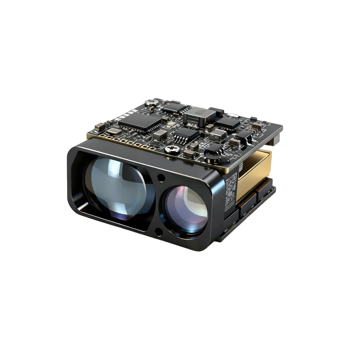
A distance sensor has to earn its place inside a compact instrument. It competes with the camera, battery, enclosure and mounting hardware for every gram and millimetre. The LRF0305C addresses that constraint with a 1535 nm pulsed time-of-flight module measuring approximately 27 × 25 × 15.5 mm and weighing approximately 14 g.[1][2]
Its appeal is the combination: a small package, a 1–10 Hz measurement rate, UART control and kilometer-class ranging under specified target and atmospheric conditions. Understanding how those requirements interact is more useful than reading “4 km” in isolation.
What fits inside a roughly 10.46 cm³ envelope?
Multiplying the nominal outer dimensions gives a bounding-box volume of about 10.46 cm³. This is a calculated geometric envelope, not the solid material volume or the complete installed space. Mounts, wiring, optical clearance and the host enclosure still need room.
| Parameter | LRF0305C manufacturer specification |
|---|---|
| Wavelength | 1535 ±5 nm |
| Module package | Approximately 27 × 25 × 15.5 mm; approximately 14 g* |
| Ranging accuracy | ±1 m; statistical basis not stated |
| Update rate / returns | 1–10 Hz / up to 3 targets |
| Transmitter / receiver optics | Beam divergence ≤0.6 mrad / receiver FOV approximately 7.4 mrad |
| Module pulse energy | ≥100 µJ |
| Supply / interface | 3–5 V DC / UART at 3.3 V TTL |
| Operating input power at 5 V | ≤0.9 W at 1 Hz; <1.5 W at 10 Hz |
| Peak input power at 5 V | <3 W; separate from average operating power |
| Module operating temperature | −40 to +70 °C; application limits discussed below |
*The module table prints mass as “≤14 ±1 g”; its envelope table prints “≤27 × 25 × 15.5 mm”, while the mechanical drawing labels length as 27 ±0.5 mm. Approximate values are used here to avoid implying an unsupported absolute limit. Release mechanical designs against the current controlled drawing and ordered configuration.[2]
For a compact inspection instrument, portable optical device or robotic sensing head, this envelope can make the difference between integrating a rangefinder within the existing design and enlarging the enclosure. Lower module mass also reduces that module’s contribution to mounting loads and rotational inertia when position and motion are otherwise equal. It does not, by itself, predict battery life or finished-system performance.
“4 km” is one test case, not every target
The LRF0305C range table includes four different cases. All carry the condition visibility greater than 8 km. The ≥4,000 m entry is for a 60%-reflective building; the same distance is not specified for a small, dark object.[1][2]
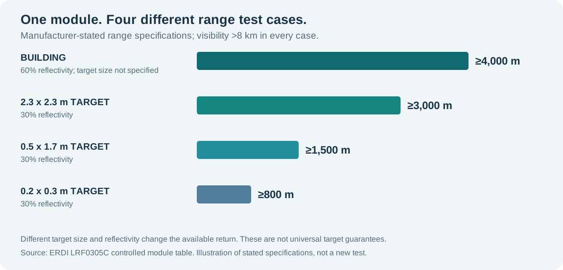
Target size matters because an illuminated surface must return enough usable light to the receiver. Reflectivity, angle of incidence, atmospheric attenuation, background illumination and optical losses all influence that return. These dependencies are central to the system analysis in Burns and colleagues’ original rangefinder paper.[3]
For selection, start with the actual object: a façade, a large diffuse panel, a narrow structure or another small target. Then match its geometry and reflectance to a relevant test case. Treat rain, fog, contamination and added windows as integration variables to be tested.
Four engineering disciplines, one small module
Pulsed time-of-flight ranging estimates distance from a measured round-trip interval: R ≈ cΔt / 2. The familiar expression approximates light propagation in air; calibrated internal delays and propagation conditions matter to absolute measurement. A successful compact design has to preserve the optical signal and its timing while meeting mechanical and electrical limits.[3][4]
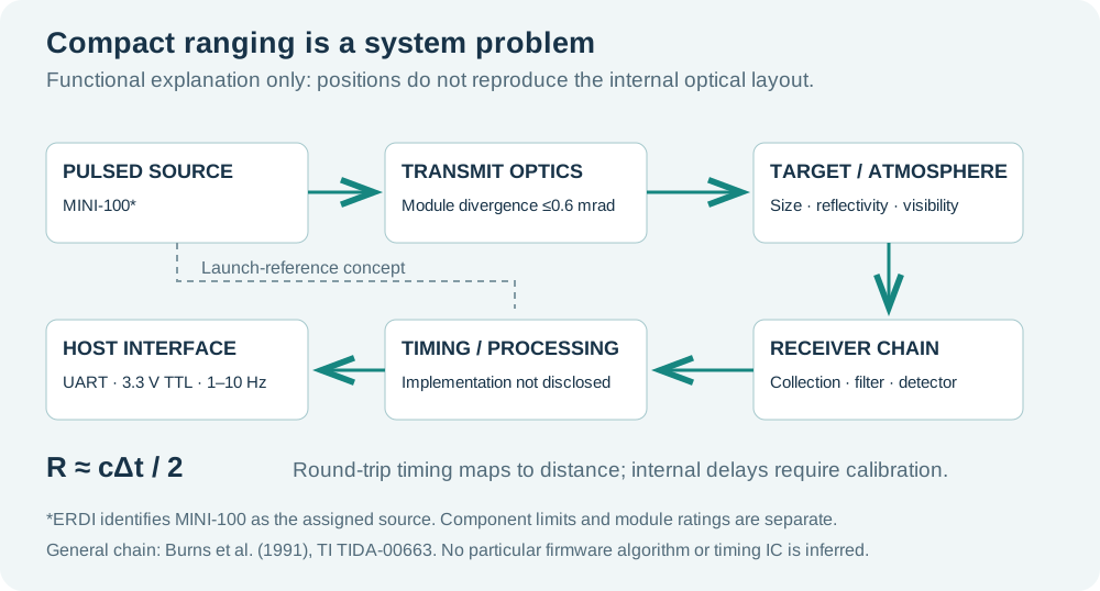
1. Optics: preserve useful return within the available aperture
The mechanical drawing identifies a 15 mm receiving aperture and a 7.9 mm transmitting aperture. The module specification separately lists ≤0.6 mrad beam divergence and approximately 7.4 mrad receiver FOV. These are different optical quantities; neither should be substituted for the other.[1][2]
Under equal uniform irradiance, equal throughput and no clipping, collected power scales with the area of a circular aperture, A = πD²/4. Larger optics can collect more return but consume package space and may also admit more background. Field of view, spectral filtering, receiver noise and alignment therefore have to be considered together.[3] Shrinking an optical instrument is a signal-budget problem as well as a packaging problem.
ERDI identifies the assigned source’s initial divergence separately from the assembled module’s divergence. That distinction illustrates why source, optics and module figures belong at different specification levels; it does not disclose the lens prescription or prove a particular folded optical path.[1]
2. Structure: allocate space without losing optical alignment
The module brings the optical apertures and electronics into a compact assembly, with a documented mounting arrangement and model-specific drawings. For the integrator, the practical task is to preserve this geometry: avoid loading the optical face, provide the specified fixing interface, protect the cable and check alignment after installation.[2]
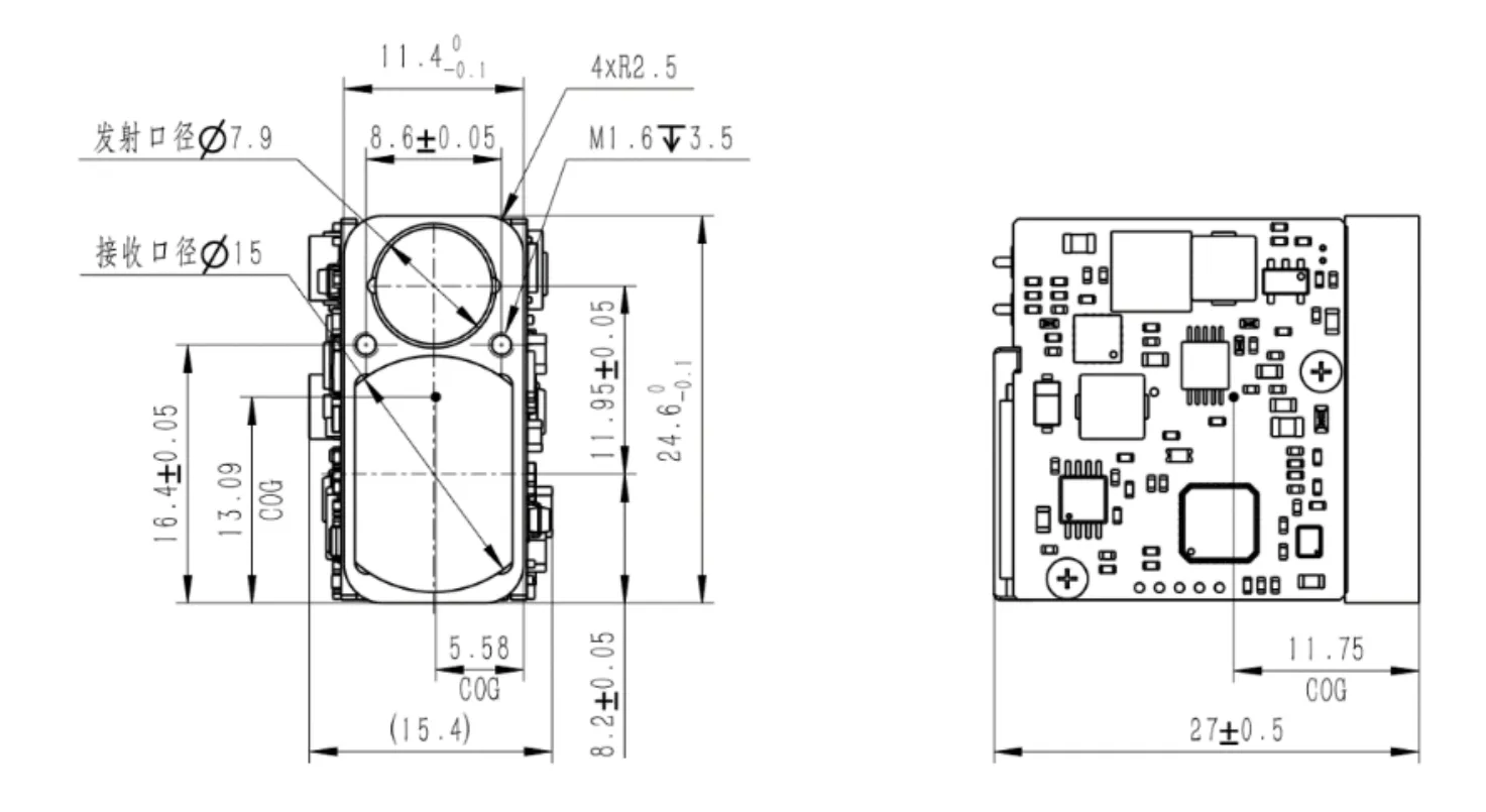
A compact module still needs an intentional optical window and thermal path. Check clear apertures, coatings and stray reflections in the final enclosure. An added window introduces optical transmission losses and reflections; validate it against the manual’s coating and geometric guidance. A tight mechanical fit is useful only if the optical path remains usable.[2]
3. Laser source: a small component, measured at the correct level
The current ERDI product record assigns MINI-100 to LRF0305C. Its separate component table lists a 14.5 × 6.3 × 4.37 mm package and 2.5 g mass; the assembled module lists laser energy ≥100 µJ. Those entries give a concrete view of the source’s packaging contribution without confusing a component with the complete rangefinder.[1]
Optical pulse duration, electrical drive duration and measurement frequency describe different things. Likewise, the source’s component drive entry is not the module’s 3–5 V supply requirement. Component environmental limits must also remain separate: the listed MINI-100 operating range is −40 to +65 °C, whereas the module table lists −40 to +70 °C. Confirm the ordered assembly’s qualification if the application approaches a boundary.[1]
4. Software and electronics: turn echoes into usable host data
LRF0305C provides UART at 3.3 V TTL, up to three target outputs, target-selection modes and diagnostic/status queries. The manual lists a factory default of 115200 bps with 8N1 framing. Follow the POWER_ON and command sequence in the current controlled manual, and confirm the document revision before implementing startup timing.[2]
The wider engineering literature explains why timing needs care. Changes in echo amplitude can shift the crossing time of a fixed threshold, while internal delays can vary with temperature and supply. Calibration and suitable signal processing address these issues in specific designs; the LRF0305C documents reviewed here do not disclose a particular correction algorithm.[4][5] Averaging can improve random precision, but also consumes acquisition time; it cannot be assumed to remove systematic drift.[6]
What does “stable performance” mean in an engineering review?
It means checking that the module delivers useful measurements consistently in the intended installation. Absolute accuracy, repeatability, valid-return rate and drift are separate properties. A fine output increment is not proof of equally fine accuracy. LRF0305C’s stated accuracy is ±1 m, even though its protocol can encode a decimal part of a metre.[2][4]
The operating-temperature rating is valuable for planning, but it is not a published full-temperature accuracy curve. The manual notes that at extreme low temperatures, accuracy within 20 m may exceed tolerance and achievable range may decrease. The reviewed documents do not provide long-term drift plots or batch-repeatability distributions.[2] A strong evaluation records target, illumination, distance, rate and temperature together, then compares repeated readings with an independent reference.
The same distinction applies to laser safety: the module document states Class 1, but no independent classification report was included in this review. The finished instrument’s accessible emission and configuration still require assessment. Handle the optical apertures and finished instrument according to the approved operating instructions.[2]
How its footprint compares with other OEM modules
The following manufacturer-published specifications provide context for the size and weight choices available to an integrator. The sources use different range conditions and are not a controlled head-to-head test.
| OEM module | Published dimensions (mm) | Published mass | 2.3 × 2.3 m target, 30% reflectance/albedo |
|---|---|---|---|
| ERDI LRF0305C[1][2] | ≈27 × 25 × 15.5 | ≈14 g* | ≥3.0 km; visibility >8 km |
| JENOPTIK DLEM 17[7] | 50 × 18 × 34 | ≤25 g | 3.3 km typical; visibility 25 km |
| Safran LRF 3013[8] | 52 × 37 × 22 | 45 g | ≥2.8 km; observer visibility 25 km |
| Safran LRF 3019[9] | 50 × 22 × 34 | 40 g | ≥4.5 km; observer visibility 25 km |
Source revisions: JENOPTIK 09/2025; Safran model sheets 2026-05; accessed 18 November 2026. Reflectance/albedo labels are retained from each source. Atmospheric visibility differs; detection criteria and test details are not fully harmonized. Do not rank range performance from these rows. JENOPTIK’s ≤1 m and Safran’s ±0.75 m accuracy entries use 1σ; ERDI’s ±1 m entry does not state that statistical basis, so an accuracy ranking is also unsupported.
LRF0305C’s clear selection argument is its approximately 27 mm package length and approximately 14 g module mass. It deserves evaluation when the design budget is around a 30 mm envelope and 15 g module mass, and its target-conditioned range meets the application. A larger rangefinder may be preferable where longer target-specific range, a different update rate or a different qualification envelope is the controlling requirement.
Bring the module into the system, not just the CAD model
- Define the measurement case. Record minimum/maximum distance, target size, reflectance, incidence angle, background and visibility.
- Verify power and host communication. Check 3–5 V supply integrity and peak transients; UART signal level is 3.3 V TTL, not RS-232. Implement the documented power-on sequence, framing, checksums and error handling.
- Test the installed optics and structure. Use the final window, enclosure and mount; check clipping, prompt reflections, contamination, boresight and temperature behaviour.
- Keep acceptance measurable. Agree accuracy, valid-return rate, repeatability and temperature tests before deployment. Request the current drawing, protocol and configuration-specific qualification documents.
The engineering value of LRF0305C is the combination of a compact optical package, low module mass and usable ranging interfaces. Its small size is a starting advantage; matching the source, optics, mechanics and host integration to the real scene is what turns that advantage into a working instrument.
Review LRF0305C for your next compact instrument
Send ERDI your target dimensions, required distance, update rate, temperature range and installation envelope. Request the current module datasheet, controlled mechanical/STEP files and interface documentation.
Review product specificationsDiscuss an integrationThe PC interface is available at erdi1535.com. Select LRF0305C and follow the current connection instructions; host hardware and serial settings must match the module.
Sources and scope
Product figures are manufacturer-stated specifications, cross-checked against the English manual. External research explains general engineering principles and is not independent validation of this model. Component specifications, module ratings and installed-system performance are kept separate. No internal lens prescription, proprietary compensation algorithm or unprovided certification is claimed.
- ERDI TECH — LRF0305C product specifications and module/component attribution
- ERDI — LRF0305C public module manual, 10 pages
- Burns, Christodoulou & Boreman (1991). System design of a pulsed laser rangefinder. Optical Engineering 30(3), 323–329. DOI: 10.1117/12.55801
- Texas Instruments. LIDAR Pulsed Time of Flight Reference Design, TIDA-00663 / TIDUCM1B, Rev. B
- Ma et al. (2022). The Short-Range, High-Accuracy Compact Pulsed Laser Ranging System. Sensors 22(6), 2146. DOI: 10.3390/s22062146
- Ari Kilpelä (2004). Pulsed time-of-flight laser range finder techniques for fast, high precision measurement applications. University of Oulu doctoral thesis, §§1.1, 2.2.2, 3.2
- JENOPTIK. DLEM family datasheet, 09/2025, p. 2, DLEM 17 column
- Safran Vectronix / Ultisense. LRF 3013 info sheet, 2026-05, p. 2
- Safran Vectronix / Ultisense. LRF 3019 info sheet, 2026-05, p. 2