

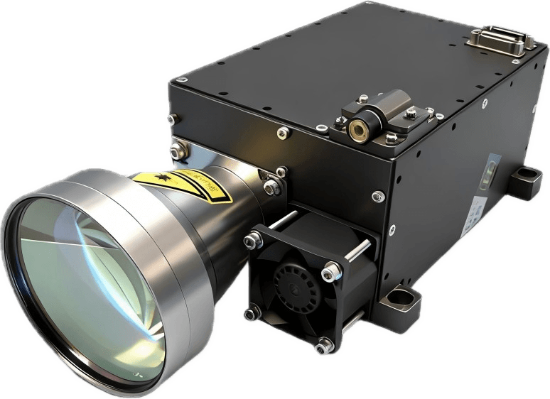
ERDI has developed a long-range laser rangefinder that places the transmitting and receiving paths behind one external objective. The product combines a 1570 ± 5 nm pulsed source, diode side pumping, electro-optic Q-switching, an adjustable 1–25 Hz ranging rate, a specified output energy of at least 15 mJ at 25 Hz, and a full-duplex RS422 interface. The supplied technical specification states a maximum range greater than 60 km under defined conditions: 80 km meteorological visibility, a 10 × 10 m typical target, and target reflectivity above 20 percent.
For platform designers, the value of this architecture is the combination of one external optical aperture, energetic nanosecond pulses and repeated long-range measurements in an integrated package. The supplied specification table lists an envelope of no more than 255 × 155 × 122 mm and a mass of no more than 2.9 kg. The mechanical drawing gives a different third dimension, so the released interface-control drawing must confirm the installation envelope. This guide explains the optical principles, performance conditions and integration requirements that matter when evaluating the product for a real platform.
1. Verified product specification and the conditions behind it
| Engineering item | Controlled value | How to interpret it |
|---|---|---|
| Ranging rate | 1–25 Hz | Selectable pulsed ranging rate. The manual also specifies a duty cycle of 60 s operation followed by 60 s rest for defined temperature test cycles; it should not be marketed as unrestricted continuous 25 Hz operation. |
| Maximum range | >60 km | Applies to the stated large target and atmospheric conditions. It is not a universal range for people, vehicles, UAVs, low-reflectivity targets, haze, rain or all aspect angles. |
| Minimum range | 300 m | Defines the near-range boundary in the supplied specification. Platform reflections, optical isolation and gating should still be evaluated in the installed system. |
| Accuracy | ≤5 m | The supplied manual does not identify RMS, one-sigma, CEP or a detailed acceptance method. A project specification should define the statistic, target and test geometry. |
| Power | 24 V DC nominal; operating <100 W; standby <10 W | Electrical design must cover startup and transient behavior, cable loss, grounding, enable control and cooling—not only average power. |
| Interface | RS422 full duplex, 115200 bps | Suitable for differential communication in electrically noisy platforms. The product also supports internal- and external-synchronous ranging. |
| Environment | Operation -40 °C to +60 °C; storage -45 °C to +65 °C | These are source specifications. No named military-standard qualification is claimed because the supplied source does not identify one. |
2. What single-aperture transmit and receive integration changes
Conventional rangefinders may expose separate transmitting and receiving apertures. A shared-aperture, or common-aperture, instrument routes both functions through one external objective. The product image and dimensional drawing show one large front objective, while the user-supplied product definition states that transmission and reception are integrated behind this single lens.
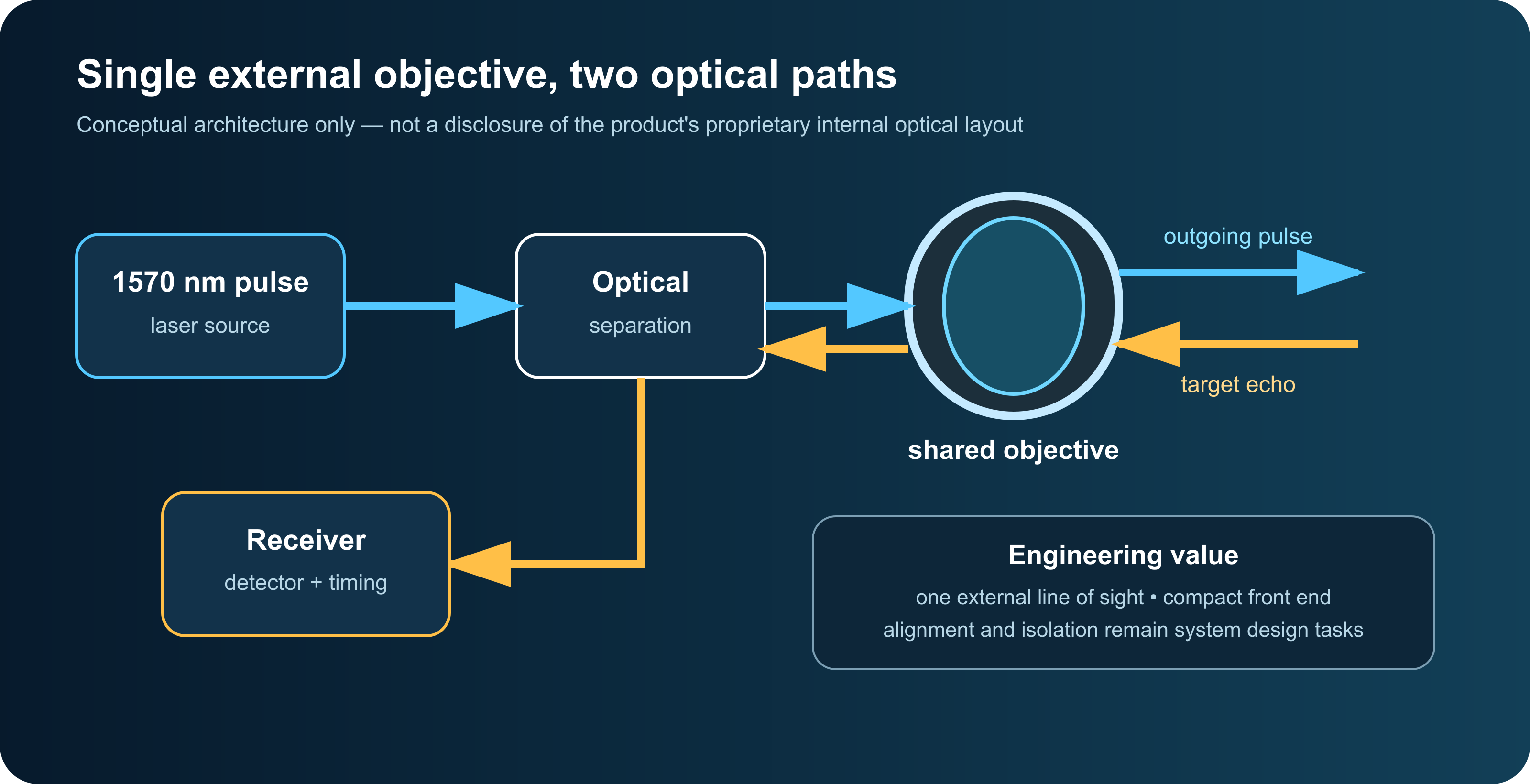
This architecture can reduce the number of large external optical assemblies and helps place the outgoing and incoming fields of view on one mechanical line of sight. It is especially useful where a host platform must align the laser channel with a camera, thermal imager, tracking telescope or stabilized gimbal. A common external objective can also simplify the front-window layout and reduce the number of apertures that must be kept clean, heated, sealed and boresighted.
Those advantages do not remove the hard optical problems. The transmitted pulse is many orders of magnitude stronger than the returning echo. The design therefore needs sufficient isolation so that internal reflections, window ghosts, scatter from the objective, electrical pickup and detector recovery do not mask a weak target return. The 300 m minimum range in the manual should be treated as a system boundary, not merely a software number: near-field isolation, receiver blanking, gate timing and the optical stack of the installed platform all matter.
3. Pulsed time-of-flight ranging and the distance equation
The instrument measures the delay between emission of a short optical pulse and detection of the echo. Because the light travels to the target and back, range is obtained from half the round-trip travel time multiplied by the pulse propagation speed. Using the path-averaged group refractive index n_g, the first-order equation is:
Here R is range, c is the exact speed of light in vacuum, 299,792,458 m/s according to NIST, and Δt is the measured round-trip delay after correcting instrument timing offsets. The group refractive index describes pulse propagation through the atmosphere. For engineering intuition, a 300 m target returns after about 2.00 µs in vacuum; a 60 km target returns after about 400.28 µs. Atmospheric refractive index, trigger delay, cable delay, detector delay and processing latency must be calibrated when absolute accuracy is important.
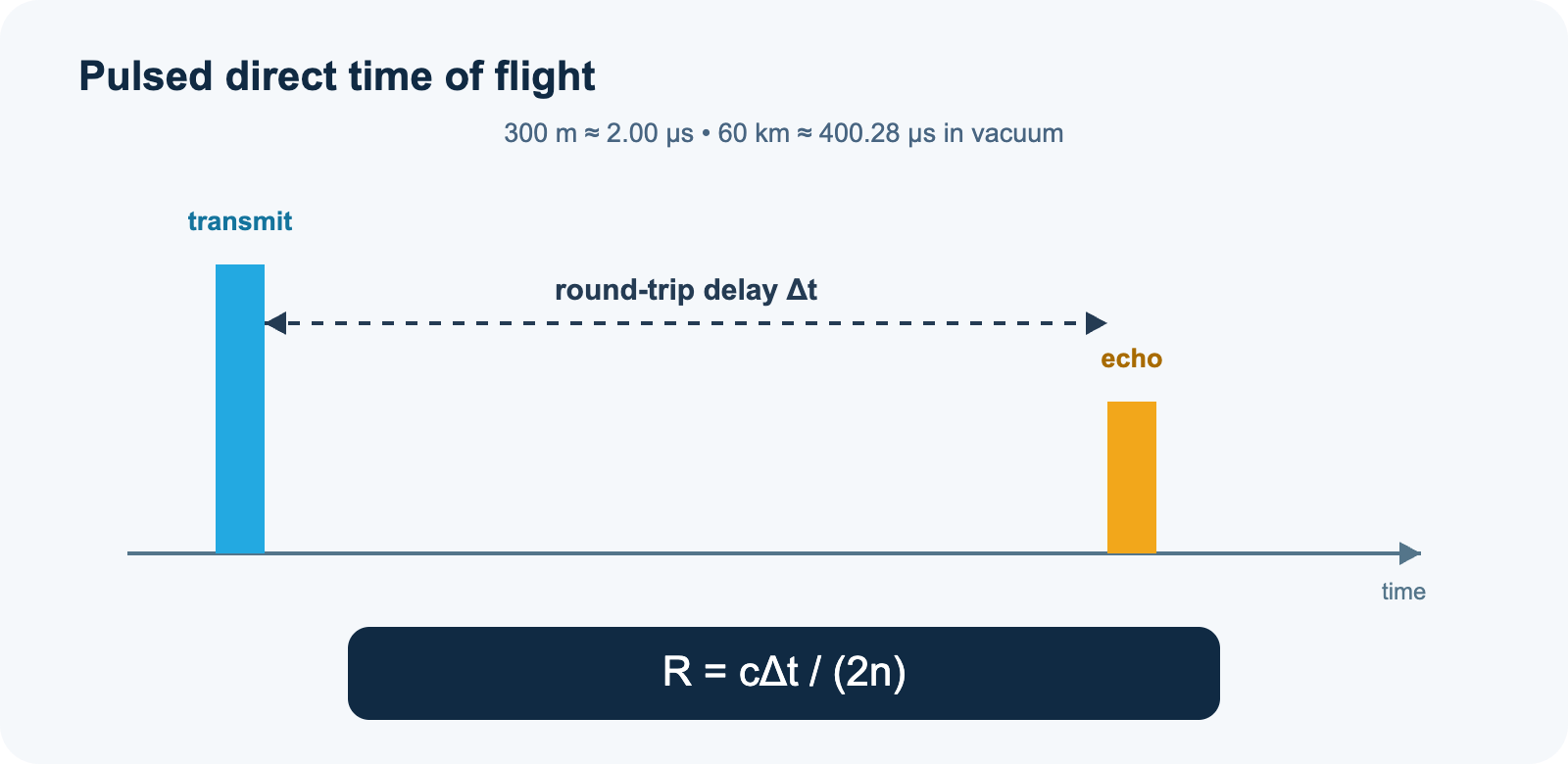
A useful timing relationship also follows from the specified ≤5 m range error: a 5 m one-way range interval corresponds to about 33.36 ns of round-trip time. That does not mean the receiver clock is only accurate to 33 ns. Real instruments can estimate pulse position with interpolation, threshold control, leading-edge or constant-fraction methods, calibration tables and multi-sample processing. Conversely, detector walk, target shape, signal amplitude and multipath can produce errors even when the electronics have a fine timing resolution.
The source pulse width is specified as 10–20 ns. In free space, that corresponds to an optical pulse length of roughly 3–6 m and a simple range-cell scale of approximately 1.5–3 m after dividing the round trip by two. Pulse width is therefore related to range resolution, but it is not identical to the final accuracy specification. Receiver bandwidth, signal-to-noise ratio, target extent and estimation method all contribute.
4. Why a 1570 nm pulsed source is used
Eye-safer spectral behavior
At visible and near-infrared wavelengths that readily reach the retina, the eye can focus a collimated beam to a small retinal spot. Around 1.5 µm, absorption in the cornea and aqueous structures is much stronger, reducing the retinal focusing hazard. This is why the 1.5 µm region is widely used in eye-safer rangefinding and lidar research. The Optica literature includes 1.57 µm optical-parametric-oscillator lidar demonstrations and describes the band’s safety advantage for time-of-flight instruments.
However, “eye-safer wavelength” and “Class 1 finished product” are different statements. IEC 60825-1 classifies the accessible emission of the complete laser product under defined conditions. The published source value of ≥15 mJ per pulse is substantial. The final product’s class therefore has to be established by measurement and the applicable accessible-emission-limit calculation; it cannot be inferred from the wavelength label.
Nanosecond pulses and peak power
Long-range direct detection benefits from concentrating optical energy into a short pulse. Using a simple rectangular-pulse estimate, 15 mJ delivered in 20 ns corresponds to 0.75 MW of instantaneous optical power. At 10 ns, the same 15 mJ would correspond to 1.5 MW. These are idealized ratios of energy to duration; actual peak power depends on the measured temporal pulse shape. At 25 Hz, 15 mJ per pulse corresponds to only 0.375 W of average emitted optical power, illustrating why peak power and average power describe very different thermal and detection problems.
Diode side pumping and electro-optic Q-switching
The manual identifies a diode side-pumped, electro-optically Q-switched source. Side pumping is a packaging method that couples diode-pump energy into the gain medium from the side, supporting energetic pulses in a mechanically integrated laser head. Q-switching stores energy in the gain medium and releases it in a short pulse. An electro-optic switch provides controlled timing suitable for synchronous ranging. The article does not infer the cavity design, crystal type or wavelength-conversion chain because those details are not in the supplied public source.
5. Why the 60 km figure needs a complete range budget
A rangefinder cannot be selected from pulse energy or wavelength alone. The echo arriving at the detector depends on the emitted energy, beam divergence, two-way atmospheric transmission, target area and reflectivity, target aspect angle, receive aperture, optical transmission, detector responsivity, electrical bandwidth, background radiation, range gate and detection threshold.
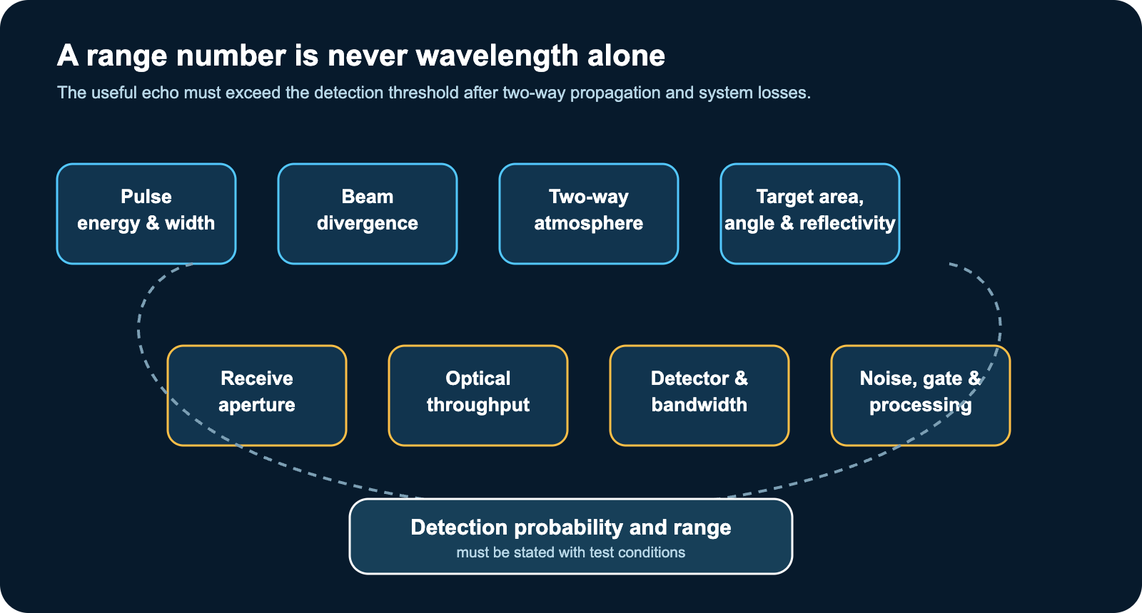
For a near-normal Lambertian hard target, a uniform beam and full receiver overlap, a useful simplified optical-energy relationship is:
E_rx is received optical pulse energy, E_t is emitted pulse energy, η_opt represents optical throughput, T²(R) is two-way atmospheric transmission, ρ is diffuse target reflectance at the laser wavelength, A_r is effective receiving-aperture area, and f_hit is the fraction of beam energy intercepted by the target. For a centered target and a uniform beam, f_hit ≈ min[1, A_t/A_b(R)], where A_t is the target’s projected area and A_b is beam area at the target. The receiving-aperture factor A_r/R² also appears in NASA Goddard’s Mercury Laser Altimeter radiometric-calibration equation; the intercepted-energy factor here extends that simplified surface-target relationship to a finite target.
When the target intercepts the complete beam, geometric received energy scales approximately as R⁻². For a fixed small target that underfills a diverging beam, A_b grows approximately as R² and geometric received energy can approach R⁻⁴, before atmospheric loss is included. Gaussian beams, target tilt, non-Lambertian scattering, pointing error and incomplete receiver overlap require a more detailed model. Optical energy must then be converted to detector signal using detector responsivity or quantum efficiency and the receiver noise model. This simplified equation explains the contributing factors; it does not predict the ERDI product’s range without the missing optical, target and detection parameters.
The specified >60 km result therefore belongs to its conditions: 80 km visibility, a 10 × 10 m typical target and reflectivity above 20 percent. Reduce target size, rotate the surface away from the sensor, introduce haze or rain, increase background radiation, contaminate the front optic, or add a lossy protective window, and the margin changes. A responsible procurement specification should state probability of detection, false-alarm probability, number of pulses, target dimensions, reflectivity, aspect, visibility, solar background, alignment, mounting vibration and temperature.
6. Beam divergence, footprint and target coupling
The manual specifies beam divergence of no more than 0.4 mrad. For a small angle, beam footprint grows approximately as D ≈ Rθ when θ is a full-angle divergence. Under that convention, 0.4 mrad gives an illustrative diameter of about 4 m at 10 km, 12 m at 30 km and 24 m at 60 km, before adding the launch aperture. If the source value is a half angle, 1/e² angle or FWHM angle, the interpretation changes. The divergence convention must therefore be fixed in the interface-control document and acceptance procedure.
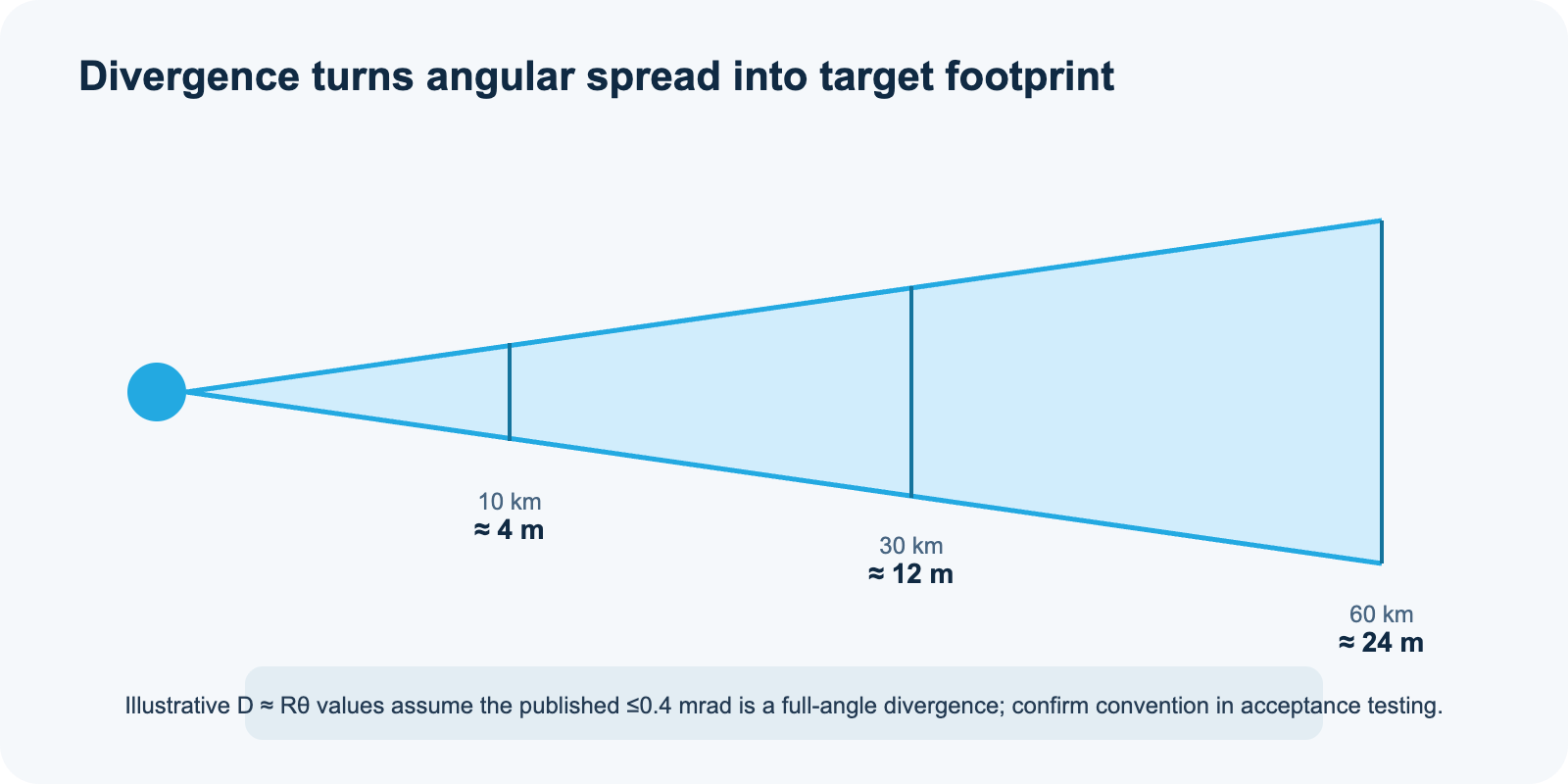
A small divergence concentrates energy on a distant target, but it also increases pointing sensitivity. At long range, small angular errors can move a significant fraction of the beam off the intended target. For a common-aperture instrument mounted beside an imaging sensor, the integration team should characterize static boresight, thermal boresight drift, vibration-induced line-of-sight motion and gimbal tracking error as one combined angular budget.
7. What 25 Hz contributes—and what it does not
A 25 Hz maximum ranging rate produces one measurement opportunity every 40 ms. Compared with a single-shot or 1 Hz instrument, a higher update rate can improve track continuity, support temporal filtering, reject isolated outliers and reduce latency in a moving platform. It can be useful for stabilized EO/IR turrets, shipborne observation, vehicle-mounted tracking, fixed-site surveillance and range instrumentation where the line of sight or target changes over time.
The manual separately specifies a 1 s single-ranging response time. The 40 ms repetition interval therefore must not be interpreted as a guaranteed command-to-result latency. The host system’s timing requirements should distinguish pulse repetition, first-result response, data-transfer delay and the rate of valid range reports.
Update rate is not identical to valid-data rate. Each pulse still needs adequate echo signal-to-noise ratio. A system may report fewer valid ranges against weak targets, in poor visibility or during rapid line-of-sight motion. Correlated errors are not removed simply by averaging more samples. The host system should record validity flags, range gates, detector health, temperatures and timing mode rather than treating every returned word as equally reliable.
The source also specifies a duty-cycle test pattern: 60 s operation followed by 60 s rest, repeated for four cycles at ambient or low temperature and four cycles at +60 °C. This condition must remain visible during integration. Cooling airflow, fan inlet clearance, enclosure pressure drop and host-platform thermal soak can determine whether a laboratory performance level is maintained in the field.
8. Mechanical, electrical and communication integration
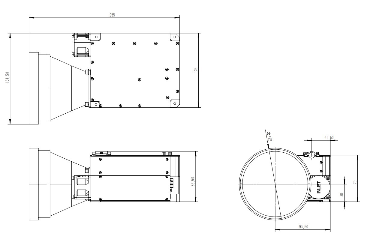
The specification table lists an envelope of no more than 255 × 155 × 122 mm and a maximum mass of 2.9 kg. A mechanical drawing in the same manual shows one dimension as 128 mm while the table states 122 mm. The installation envelope remains subject to confirmation from the released mechanical interface-control drawing. Machining, clearance and enclosure decisions must use the approved CAD/ICD revision that resolves this conflict.
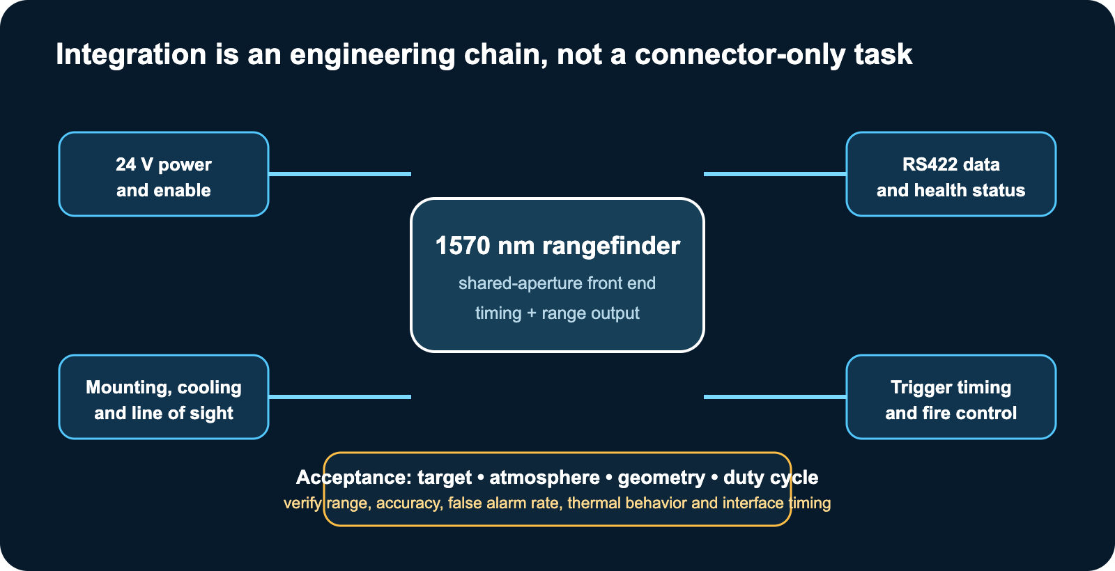
The rangefinder uses a nominal 24 V supply, with the source specifying 24 V ±4 V in one table and +24 V DC ±10 percent in the interface section. This is another item for the project ICD. The integrator should define input transient limits, brownout behavior, inrush, reverse-polarity protection, grounding and shielding. Operating consumption is specified below 100 W and standby below 10 W. Cable gauge, connector temperature rise and power-switch margin should be selected against worst-case conditions, not a nominal bench reading.
The communication interface is full-duplex RS422 at 115200 bps with one start bit, eight data bits, one stop bit and no parity. Differential signaling is appropriate for platform installations, but correct termination, reference grounding, shield strategy and cable topology remain essential. Internal-synchronous and external-synchronous ranging modes support different host architectures. The manual specifies an external synchronization signal-to-laser-emission delay of 304.0 µs ±0.1 µs; system timing validation should measure this at temperature and include the complete host trigger path.
9. Environmental design and qualification boundaries
The supplied source lists operation from -40 °C to +60 °C, storage from -45 °C to +65 °C, and a damp-heat condition of 95 percent ±3 percent relative humidity at +35 °C ±2 °C for 72 h. It also lists a half-sine shock of 10 g for 11 ms, three-axis vibration, and six temperature cycles between -40 °C and +60 °C at 3 °C/min with one-hour storage intervals.
These entries are useful design inputs, but they are not enough to claim compliance with a named military or civil environmental standard. A released qualification report should identify the test standard, axis, fixture, powered or unpowered state, operating checks, sample quantity and acceptance criteria. For a shared-aperture sensor, post-test optical alignment and range verification are as important as a basic power-on check.
10. Application scenarios that match the architecture
Long-range electro-optical observation
In an EO/IR system, the rangefinder can add direct distance data to imagery and angular tracking. The shared external objective can support a compact front-end arrangement, while external synchronization can align ranging events with camera frames or tracking logic. Platform designers should verify laser-to-imager boresight across temperature and zoom states.
Coastal, border and fixed-site surveillance
Large structures, vessels and other extended targets can present a stronger echo than small targets, but marine aerosol, haze, mirage, window contamination and target aspect can dominate the range budget. The >60 km source condition is most relevant to large targets in exceptionally clear visibility; it should not be converted into an unconditional surveillance radius.
Vehicle- and ship-mounted tracking systems
A 1–25 Hz update range and RS422 interface can support a host tracker that needs repeated distance observations. Vehicle vibration, exhaust plume, window heating, electromagnetic compatibility and stabilization error should be included in the acceptance plan. The 2.9 kg module mass and <100 W operating-power limit also affect gimbal inertia and thermal design.
Airborne payloads with sufficient SWaP capacity
The module may suit aircraft or larger unmanned platforms that can accommodate its mass, envelope, peak electrical demand and cooling needs. It should not be promoted as a micro-UAV sensor. Airworthiness, laser-use rules, line-of-sight safety analysis and platform vibration qualification remain the responsibility of the final system program.
Range instrumentation and research platforms
External trigger control, known timing, high-energy nanosecond pulses and status telemetry can support experimental tracking and range-instrumentation systems. Researchers should capture raw validity information and environmental conditions so that detection probability and bias can be separated from simple successful-range examples.
11. A practical acceptance plan
- Freeze the configuration. Record hardware revision, firmware version, optical window, cable set, cooling arrangement and host trigger mode.
- Define targets. State dimensions, material, reflectivity at 1570 nm, surface angle and whether the target fills the beam footprint.
- Record the atmosphere. Measure visibility or extinction, humidity, temperature, precipitation, solar background and path geometry.
- Measure the timing chain. Verify external-trigger delay, timestamp alignment, communication latency and range bias over temperature.
- Measure probability, not anecdotes. Report valid-range probability and false-alarm probability over a declared number of pulses and range gates.
- Test optical isolation. Check near-range ghosts, host-window reflections, contamination, detector recovery and minimum-range behavior.
- Verify thermal duty. Repeat the required operating/rest cycle and monitor case, diode, receiver and ambient temperatures.
- Recheck boresight. Measure alignment before and after shock, vibration and temperature cycling.
- Complete laser-safety classification. Evaluate accessible emission for every operating mode and foreseeable fault in the final product under IEC 60825-1 or the applicable regional standard.
12. Frequently asked questions
Does 1570 nm automatically make the rangefinder IEC Class 1?
No. The wavelength provides an eye-safer physical basis than retinal-hazard wavelengths, but the class of a complete product depends on accessible emission, pulse energy, pulse width, repetition rate, divergence, aperture and operating conditions. The supplied manual does not include a Class 1 report, so ERDI and the system integrator should provide classification evidence for the final configuration.
What does the stated range beyond 60 km mean?
It means the source specification reports >60 km when meteorological visibility is 80 km, the typical target is 10 × 10 m, and target reflectivity is greater than 20 percent. It is not a guaranteed distance for every target, atmosphere or viewing angle.
Why use one external objective for transmit and receive?
A common external aperture can reduce front-end optical duplication and place the outgoing and incoming paths on one mechanical line of sight. It can simplify packaging and alignment at the platform level. It also creates demanding isolation and ghost-control requirements, which must be engineered and tested.
Does 25 Hz mean 25 valid measurements every second?
It means up to 25 ranging opportunities per second under the specified operating mode. Valid-data rate still depends on echo strength, background, target motion, range gating, atmosphere and system thresholds. The source duty-cycle requirement also applies.
What information should an OEM provide before integration?
At minimum: released mechanical ICD, connector and electrical limits, protocol revision, trigger timing, range-validity/status definitions, cooling requirements, optical-window requirements, acceptance-test method, laser-safety classification evidence, firmware revision and configuration-control process.
13. References and evidence boundary
- ERDI TECH LTD, 1570 nm Laser Rangefinder User Manual, v1.0, September 2026, user-supplied controlled source used for all product-specific values in this article.
- IEC 60825-1:2014, Safety of laser products — Part 1: Equipment classification and requirements. The standard establishes product classification from accessible emission; wavelength alone is not a product class.
- NIST, CODATA value of the speed of light in vacuum, 299,792,458 m/s exactly, physics.nist.gov.
- L. Andersson, I. Renhorn, S. Nilsson and T. Klinga, “High Power Pulsed Semiconductor Laser for Eyesafe Laser Range Finders,” CLEO Europe 1996, DOI: 10.1364/CLEO_EUROPE.1996.CThI82.
- S. H. Klein, W. E. Wilcox and D. K. Killinger, “Range-resolved lidar measurements of the atmosphere using an eye-safe infrared KTP optical parametric oscillator,” Optical Remote Sensing of the Atmosphere 1997, DOI: 10.1364/ORSA.1997.OWC.6.
- NASA Jet Propulsion Laboratory, Lidar 101, used for general time-resolved lidar principles.
- NASA Goddard Space Flight Center, Recalibrated MLA Radiometric Data Records, equation 1 and the associated reference X. Sun and G. A. Neumann, “Calibration of the Mercury Laser Altimeter on the MESSENGER Spacecraft,” IEEE Transactions on Geoscience and Remote Sensing 53(5), 2860–2874 (2015), DOI: 10.1109/TGRS.2014.2366080. Used for the receiving-aperture and range dependence of a diffuse surface return.
External literature is cited only for general physics and safety principles. It is not evidence that this ERDI product has any parameter, certification or performance beyond the values and conditions reproduced from the supplied manual.
Discuss your integration envelope with ERDI
For optical-interface review, trigger timing, platform power and cooling, target-specific range-budget analysis, or a controlled acceptance plan, contact ERDI engineering. Start with the real target size, reflectivity, visibility, update rate, window material, mounting environment and required laser-safety class.
Contact ERDI engineering · Explore ERDI laser rangefinder modules · Read the 905 nm high-repetition-rate engineering guide