

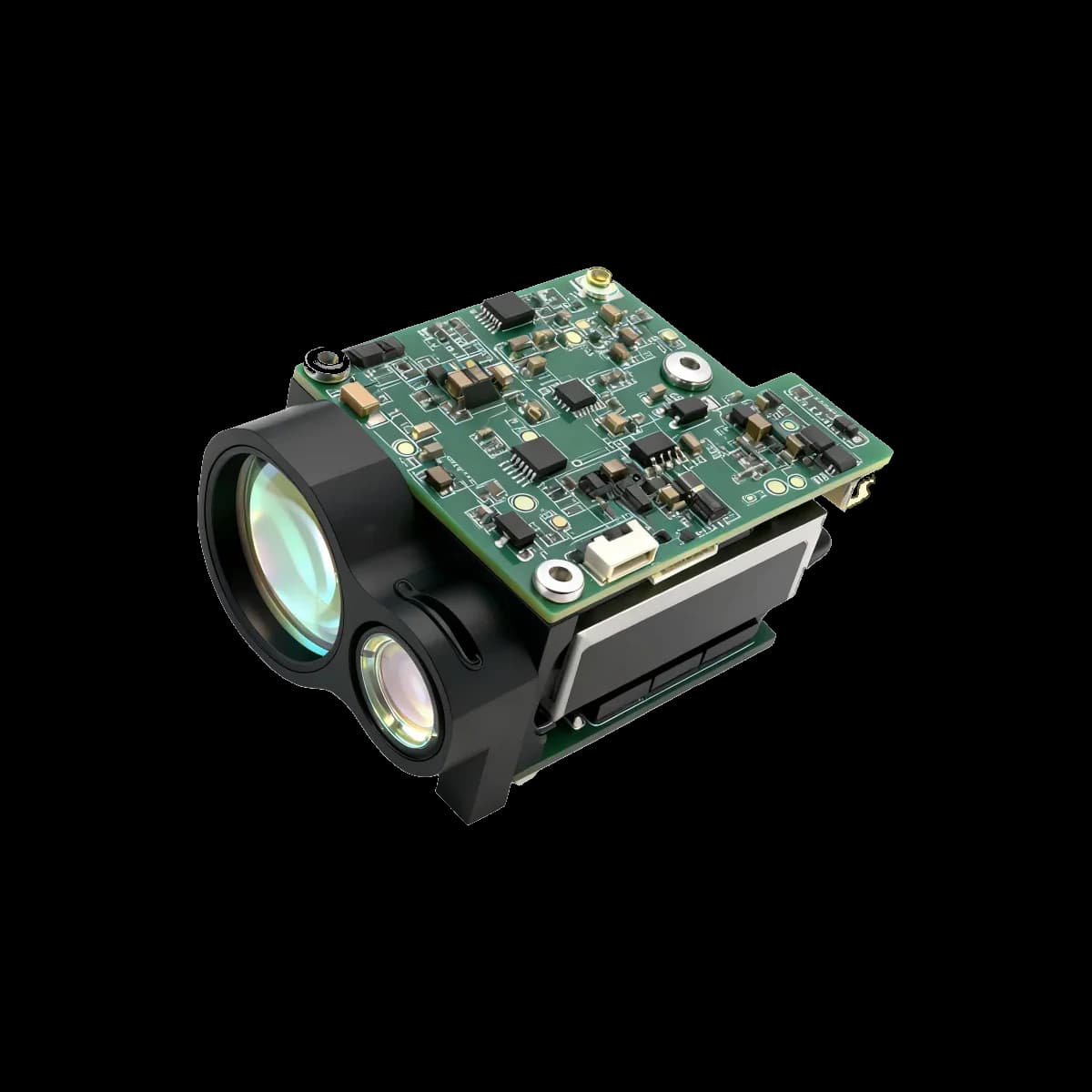
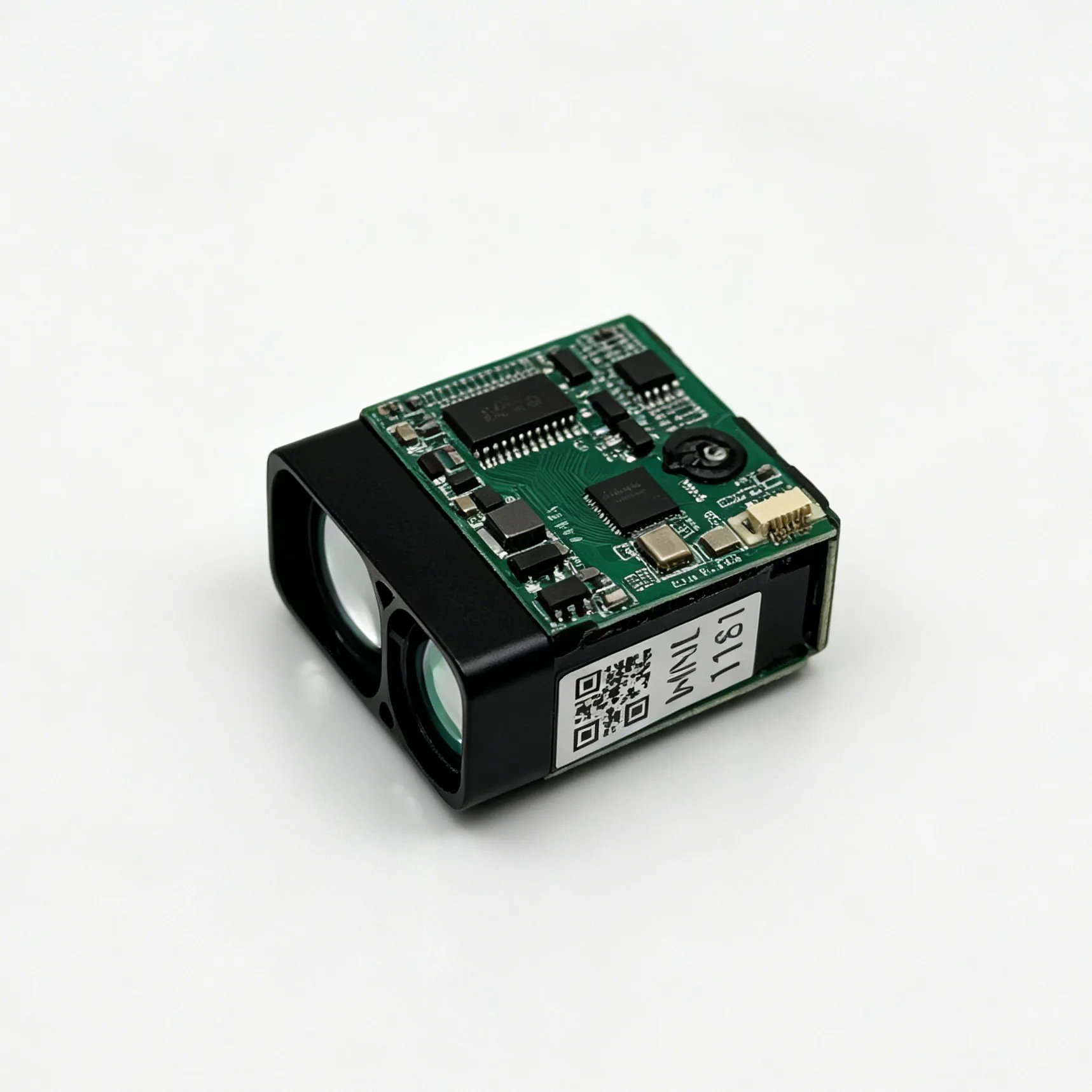
Compact laser rangefinder design is a balance of optical performance, receiver sensitivity, mechanical stability, power, heat and host integration. Reducing one dimension can affect aperture, alignment tolerance or thermal margin elsewhere, so module selection and packaging should be treated as a system-level optimization rather than a single size or range comparison.
Core engineering trade-offs
| Constraint | Design impact | What to verify |
|---|---|---|
| Receiver aperture | A smaller aperture collects less return energy. | Range under defined target reflectivity and visibility |
| Beam divergence | Controls spot size, alignment tolerance and target discrimination. | Specified divergence and measurement method |
| Module dimensions | Limit optical path, mounting features and connector access. | Mechanical drawing, keep-out zones and optical axes |
| Mass | Affects handheld balance, gimbal inertia and UAV endurance. | Installed mass including bracket and harness |
| Power | Sets battery, regulator and thermal requirements. | Supply range, peak current, average power and duty cycle |
| Measurement rate | Influences moving-target updates and internal heat. | Supported rates, latency and sustained operating limits |
Optical design considerations
The transmitter, receiver and host optics must share a stable reference. The finished enclosure should preserve clear transmit and receive apertures without vignetting or internal reflections. Window material and coatings must be characterized at 1535 nm, and boresight should be checked after assembly, thermal cycling and vibration.
Maximum range is meaningful only when the supplier states the target reflectivity and size, atmospheric visibility, detection probability, aperture and signal-processing criteria used during testing.
Mechanical and thermal design
- Use the specified locating features and mounting torque from the mechanical drawing.
- Avoid housing distortion that can shift optical alignment.
- Include the module, connector, cable and bracket in mass and center-of-gravity calculations.
- Provide a documented heat path to the host enclosure when the module requires conductive cooling.
- Check alignment and range bias across the intended temperature and vibration environment.
Electrical interface and timing
The host design should confirm supply tolerance, startup behavior, peak current, grounding, logic levels, connector pinout and communication protocol from the current interface control document. For moving platforms, also measure command latency, result latency and timestamp alignment with cameras, navigation sensors or industrial controllers.
Range and eye-safety claims
A 1535 nm source can support a lower retinal-hazard design, but wavelength alone does not establish a finished product's laser class. Pulse energy, repetition rate, divergence, aperture, optics and exposure conditions all matter. Integrators should verify the complete assembly against the standards required for its market and intended use.
Likewise, no wavelength guarantees operation through fog, smoke or rain. Atmospheric attenuation depends on visibility, particle size, path length and receiver design. Test the selected module under representative conditions instead of relying on a general wavelength claim.
Validation plan for a compact module
- Establish baseline range, accuracy and no-return behavior with traceable targets.
- Measure boresight and range bias after installation.
- Run the required temperature, vibration, shock, humidity and sealing tests on the finished assembly.
- Repeat optical and electrical measurements after environmental testing.
- Document firmware version, configuration, calibration data and acceptance limits.
Typical applications
- UAV and EO/IR payloads where mass, volume and power are tightly limited
- Handheld binoculars, thermal imagers and observation instruments
- Robotics, perimeter monitoring and industrial distance measurement
- Portable mapping and surveying equipment
Supplier documentation to request
- Performance test conditions and acceptance criteria
- Mechanical drawing and optical-axis definition
- Interface control document and timing information
- Environmental qualification summary
- Eye-safety test scope and finished-system responsibilities
- Evaluation sample and integration support process
Compare compact 1535 nm modules
Browse ERDI's 1535 nm laser rangefinder module collection, or send your target, range, accuracy, SWaP and interface requirements to sales@erdicn.com.