
.png?w=1200&h=1200&q=80)
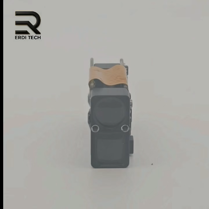
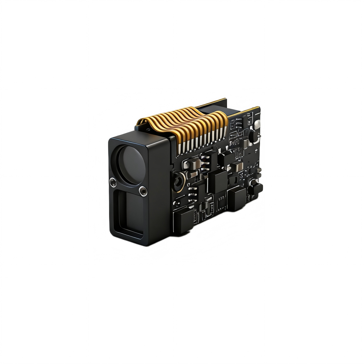
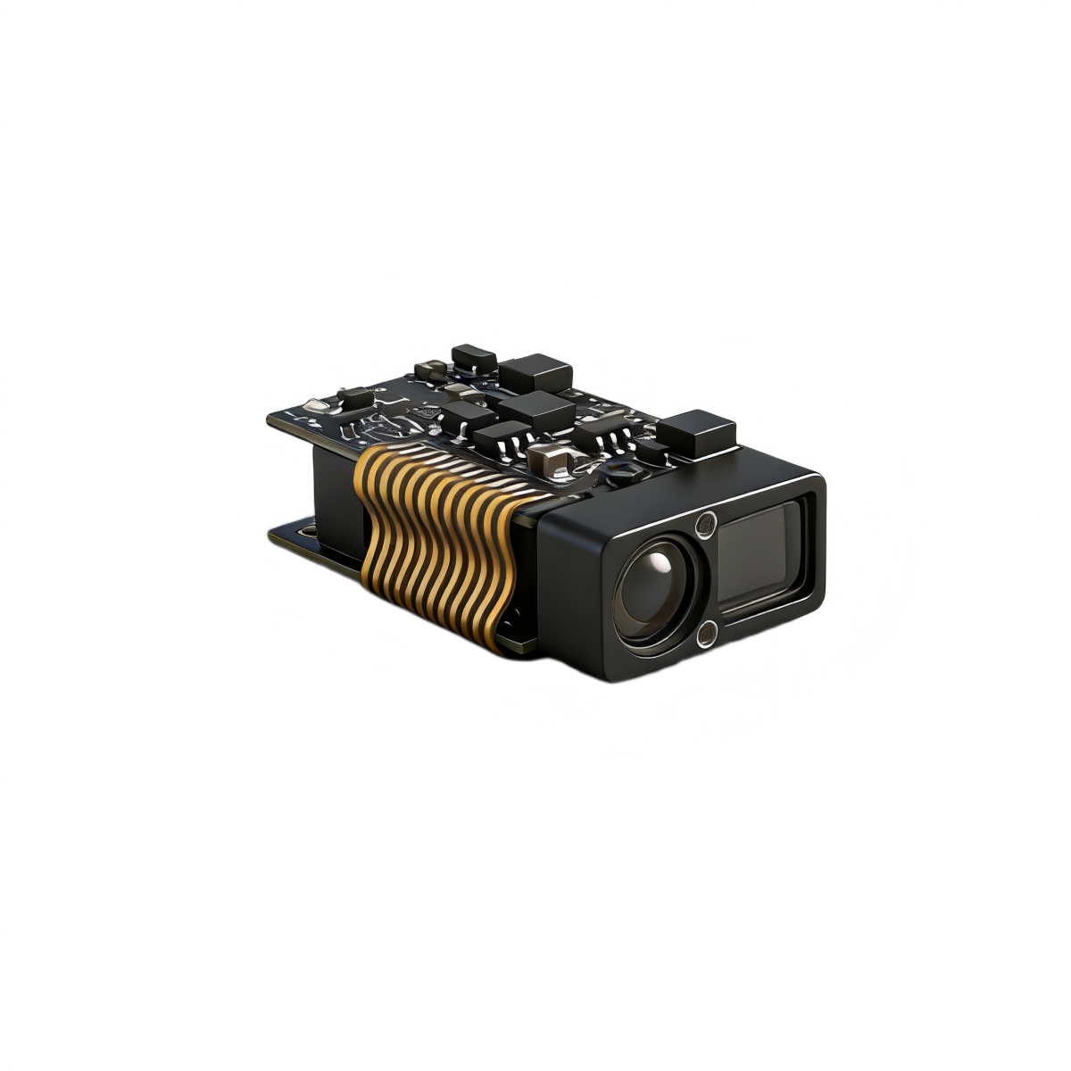
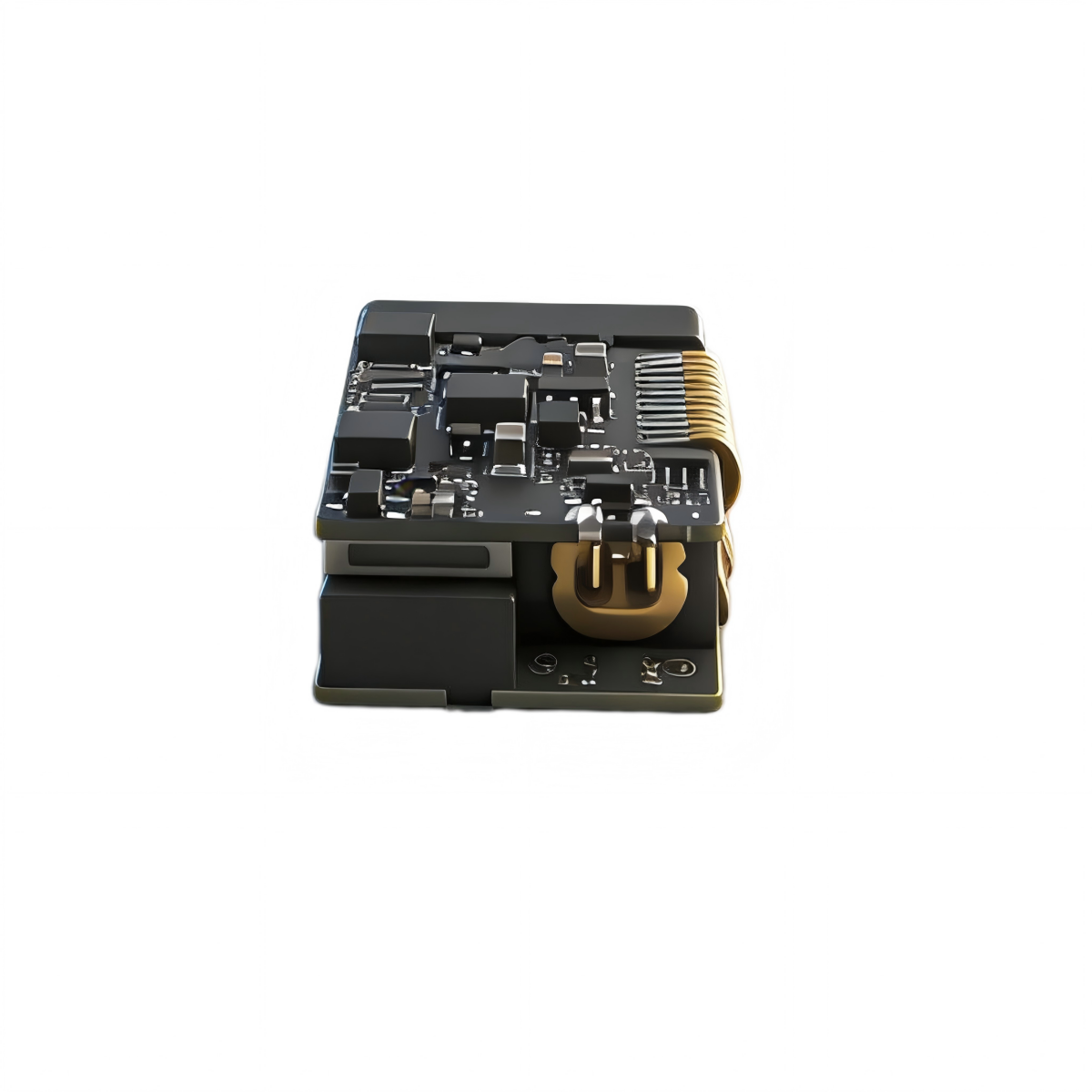
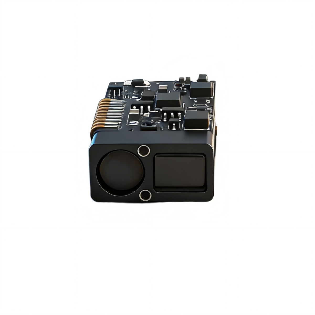
SPD1200M2 Micro 905nm Distance Engine for Thermal Imaging, Night Vision and Civil UAVs
Contact Us

Senior Engineer, Yilin
Tel : +86 28 81076698
WhatsApp : +86 18000520222
ERDI Pre-Sales Notice & Customer Information
(Please Read Before Purchase or Inquiry) Thank you for your interest in ERDI TECH LTD. We are committed to providing customers worldwide with high-precision, high-reliability laser products and technical solutions. Before placing an order, please read the following information carefully to better understand our company, services, and purchasing policies.
-
About ERDI
ERDI is a professional manufacturer specializing in the research, development, and production of laser modules, laser measurement systems, and related optoelectronic components.
We integrate design, R&D, production, and sales, with a focus on safety, innovation, and precision.Our products are widely used in:
- Industrial measurement and alignment systems
- Scientific research and educational applications
- Optical instrumentation and laser testing
- Consumer and OEM laser solutions
ERDI operates certified facilities and maintains rigorous quality control to ensure that every product meets international standards.
-
Global Presence and Trade Reliability
ERDI has established official stores on leading global platforms including Amazon, Alibaba International Station, and Made-in-China.com, allowing customers worldwide to purchase safely and conveniently. We are a verified and trusted factory, not a reseller, and we ensure that all transactions, quotations, and logistics follow transparent and secure trade practices. -
Sample and Lead Time
To help customers evaluate our products and performance, we offer sample orders for most product categories.
- Standard samplesare typically delivered within one week after order confirmation.
- Customized modulesmay require additional processing time depending on design complexity and optical requirements.
Our logistics team will provide real-time tracking and documentation for every shipment.
-
OEM / ODM / OBM Services
ERDI supports full-range customization including:
- OEM (Original Equipment Manufacturing)– Products manufactured under your brand or part number.
- ODM (Original Design Manufacturing)– Custom optical or mechanical design based on your specifications.
- OBM (Original Brand Manufacturing)– Private-label solutions with our in-house R&D and branding support.
We provide technical co-development, logo engraving, packaging customization, and batch production services to meet both small-scale and mass-production requirements.
-
Technical Support and Service System
ERDI maintains technical service centers and distribution partners worldwide, enabling rapid customer response.
We provide:- Comprehensive technical consultation and project evaluation
- One-on-one on-site technical assistanceat the customer’s facility when required
- Lifetime after-sales supportand technical maintenance guidance
Each laser product is delivered with a full set of user documentation, including Laser Module Usage Precautions and Safety Guidelines.
-
Quality Assurance and Warranty
ERDI implements strict multi-stage quality control throughout production:
- Incoming material inspection
- Optical alignment verification
- Output power and wavelength calibration
- Safety and durability testing under standard conditions
We guarantee that all products leaving our factory meet design and performance specifications.
Except for man-made damage, we will replace any defective unit within one year free of charge and provide lifetime maintenance support thereafter.For more details, please refer to our After-Sales Service & Warranty Policy.
-
Important Safety Reminder
Before using any ERDI laser product:
- Carefully read and follow the Laser Module Usage Precautions.
- Always use appropriate laser protective eyewear.
- Operate only in controlled environmentsunder trained personnel supervision.
Failure to observe safety instructions may result in injury or equipment damage.
-
Communication and Order Confirmation
To ensure efficient service, please confirm the following before placing an order:
- Product model, wavelength, output power, and working voltage/current
- Whether you require custom mechanical dimensions, optical configurations, or driver circuitry.
- Packaging, labeling, and shipping preferences.
- Any specific export or compliance documentation needed for your country.
Our sales engineers will provide an official quotation and delivery schedule upon confirmation of all specifications.
-
Final Statement
ERDI upholds the values of safety, integrity, and precision. We sincerely welcome customers from all over the world to visit our facilities, discuss cooperation, and experience our advanced laser technologies firsthand. Your satisfaction and trust are our highest pursuit.
After-Sales Service & Warranty Policy
We strive to provide high-quality laser modules and excellent customer service. Please read the following terms carefully to understand your rights and our responsibilities.
-
Product Origin and Quality Assurance
- All ERDI products are manufactured directly by the factory, ensuring consistent quality and full traceability.
- We provide a diverse rangeof laser modules and laser distance measurement modules to suit various industrial, educational, and research applications.
- Every product is tested and inspectedbefore shipment to guarantee that it meets specification standards.
-
Return and Exchange Policy
- Customers may request a return or exchange within 30 daysof receiving the goods, provided that:
- The product remains in original condition, unused, and without affecting secondary sales.
- A valid reason for return or exchangeis provided.
- Upon approval, we will replace or refund according to our service policy.
- The buyer is responsible for shipping costsassociated with returns, exchanges, or repairs, based on international freight cost rules.
-
Warranty Coverage
- The main functional componentsof ERDI laser products are covered by a 2-year warranty from the date of purchase, excluding cosmetic appearance.
- Within the first 12 months, if a verified manufacturing defect occurs, we will replace the item with a brand-new productfree of charge.
- Replacement of cosmetic or housing components (e.g., enclosure, labeling, or exterior parts) may incur a reasonable cost feebased on material expenses.
- Warranty does not cover:
- Damage due to misuse, improper installation, or modification.
- Operation outside the recommended power supply or temperature range.
- Accidental or physical damage, including drops, fire, or liquid ingress.
-
Receiving Inspection
- Upon delivery, please inspect the parcel immediately in the presence of the courier.
- If there is any quantity discrepancy, visible damage, or mismatch, do not signthe delivery receipt.
- Once the package is signed for (by you, family, or colleagues), it is considered accepted as correct and complete.
-
Customer Support
For technical assistance, warranty claims, or safety inquiries, please contact our official service team through the contact information listed on erdicn.com.
Our support engineers will provide professional guidance on installation, alignment, safety, and maintenance procedures.
Laser Module Usage Precautions
(Important – Buyers Must Read Before Use)
Operating laser modules involves potential optical and thermal hazards. To ensure safe and proper use, please read the following precautions carefully before powering on your laser product.
-
General Safety Warnings
- Invisible Radiation Warning– Some laser modules emit infrared (IR) or ultraviolet (UV) radiation that is invisible to the human eye. Never assume the laser is malfunctioning simply because you cannot see the beam. Always confirm that the power is disconnected before inspecting the module.
- Do Not Look Directly into the Laser Aperture– Even when wearing certified laser safety goggles, never stare directly into or near the beam exit of a working laser module.
- Avoid Reflected Beams from High-Power Lasers– Reflection from Class IV lasers (output power > 500 mW) can cause severe and permanent eye damage. Always wear wavelength-specific safety goggles when operating or aligning high-power laser systems.
- Keep Away from Flammable Materials– Do not place flammable or explosive items (such as paper, cloth, leather, or plastics) in the laser path. Black or dark-colored materials absorb laser energy more easily and may ignite. (Exception: controlled material-burning experiments with proper fire protection.)
- Avoid Direct Human Exposure– Class IIIa or higher lasers (≥ 5 mW) can burn skin or eyes. Never point a laser beam at any part of a person’s body. Restrict Access to Trained Personnel Only – Keep all laser devices out of reach of untrained individuals, children, and pets.
-
Optical Path and Reflection Safety
- Never Aim Toward Glass Surfaces– Ordinary glass reflects roughly 4 % of incident light, which can redirect dangerous laser radiation into your eyes. Avoid operating lasers in front of mirrors or reflective windows.
- Working Plane Awareness– When setting up an experimental platform, note the laser emission height. Do not position your head or eyes near this level during operation. Lenses and mirrors may reflect or refract light unexpectedly. Always align optical components downward or horizontally—never angle a beam upward.
- Remove Reflective Accessories– Watches, jewelry, and other shiny objects can reflect laser light unpredictably. Remove them before use.
- Infrared Beam Detection– IR lasers (wavelength > 800 nm) are almost completely invisible. Use a beam-viewing card, IR detector, or up-conversion screen to visualize the beam path safely.
- Visual Brightness Misjudgment– Some wavelengths (below 430 nm or above 700 nm) appear much dimmer than their actual power output. Do not rely on visual brightness to judge beam intensity.
- Pulsed Laser Caution– Pulsed lasers can have extremely high peak power even at modest average power levels. Verify that all optical elements and samples in your experiment exceed the laser’s damage threshold before exposure.
- Prohibited Uses– It is strictly forbidden to point laser beams at moving vehicles, aircraft, or any area where light could distract or endanger others.
- End-of-Beam Safety Stop– Always place a black anodized or matte metal plate at the end of your optical path to absorb residual energy and prevent laser leakage into surrounding areas.
Low-Power Modules – ERDI laser modules rated below 1 mW are considered eye-safe under normal operating conditions and can be used without hazard when handled properly.
-
Recommended Protective Measures
- Protective Eyewear– Always wear certified laser safety goggles designed for the specific wavelength and power level of your module.
- Appropriate Clothing– Light-colored or white long-sleeved clothing reduces the risk of heat absorption or ignition if stray laser light contacts the fabric.
- UV Laser Protection– For ultraviolet lasers, apply broad-spectrum sunscreen (SPF 30 or higher) to exposed skin areas to minimize UV radiation effects.
- Environmental Safety– Operate lasers in a controlled laboratory or industrial environment with minimal reflective surfaces. Ensure that all personnel nearby are informed of ongoing laser use and have received proper training.
Technical Specifications
|
No. |
Parameter |
Specification |
|
1 |
Laser Wavelength |
905 nm ± 5 nm |
|
2 |
Laser Beam Divergence |
< 4mrad |
|
3 |
Optical Material |
PMMA |
|
4 |
Receiving Aperture |
5.0mm × 7mm |
|
5 |
Measurement Range |
0.2 m – 1200 m Note: The measurement range may be reduced under strong sunlight or low-visibility conditions. |
|
6 |
Ranging Accuracy |
±0.3m (≤100m) ±0.3m+d*0.7‰ (100m<d<1200m) |
|
7 |
Measurement Frequency |
2 Hz – 15 Hz or 4 Hz – 15 Hz Adaptive |
|
8 |
Measurement Accuracy Rate |
≥ 98% |
|
9 |
False Alarm Rate |
≤ 1% |
|
10 |
Communication Interface |
UART-TTL (Customizable) |
|
11 |
Baud Rate |
Default 115200 bps |
|
12 |
Supply Voltage |
3.3 V – 5 V |
|
13 |
Startup Time |
≤ 200 ms |
|
14 |
Inrush Current |
≈ 380 mA |
|
15 |
Operating Power Consumption |
Average Power Consumption ≈ 0.45 W Maximum Power Consumption ≤ 0.75 W |
|
16 |
Operating Temperature |
-20°C to +60°C |
|
17 |
Storage Temperature |
-30°C to +70°C |
|
18 |
Protection Rating |
IP67 (Inside Lens Cavity) |
|
19 |
Laser Safety Class |
IEC Class I |
|
20 |
Dimensions |
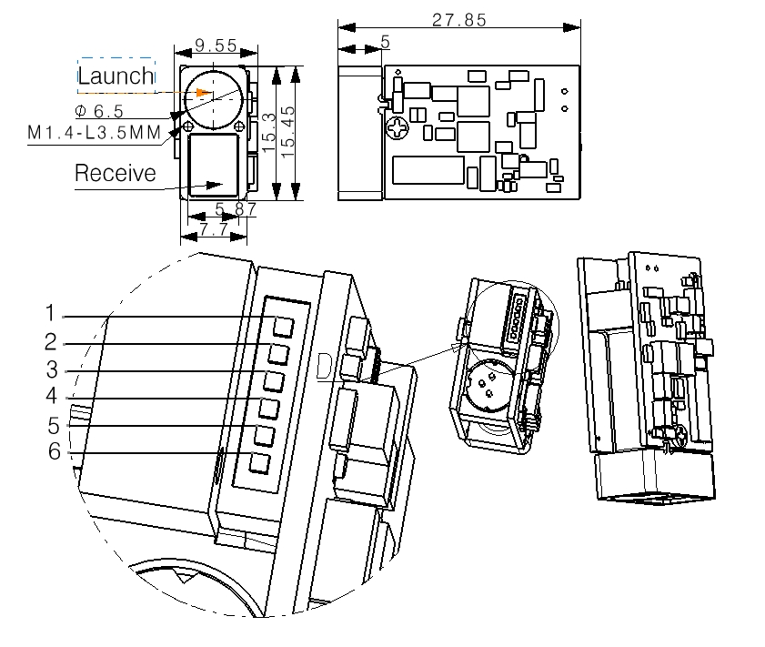
7.7 mm × 15.3 mm × 27.85 mm (Rectangular) |
|
21 |
Weight |
≈ 6 g |
|
22 |
Shock Resistance |
1000 g/ms (10 times/s along optical axis) |
|
23 |
Vibration Resistance |
5–50–5 Hz, 1 octave/min, 2.5 g |
|
24 |
Reliability |
MTBF ≥ 1500 h |
Functional Description
The system supports single measurement and continuous measurement functions.
1 Baud Rate Configuration
Allows modification of the serial communication baud rate.
2 Single Measurement
Triggers a single distance measurement to the target. For low-reflectivity targets, the system automatically repeats measurements until stable distance data is obtained. The final result is transmitted via the serial interface in the standard data format.
3 Continuous Measurement
In continuous measurement mode, the laser module performs repeated distance measurements on the target. The typical refresh rate can be set to 2 Hz, and the maximum refresh rate can reach 15 Hz.
Electrical Interface Definition
|
Pin |
Definition |
Description |
|
1 |
GND |
Power − |
|
2 |
VCC |
Power + |
|
3 |
I/O (Reserved) |
Reserved for expansion |
|
4 |
TXD |
Signal output port, Ranging Module → Host |
|
5 |
RXD |
Signal input port, Host → Ranging Module |
|
6 |
SW-SHOT |
Function Enable (active high) Note: Compatible with active-low control requirements |
Mechanical Interface
Product Description
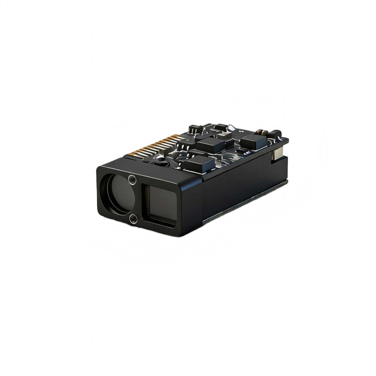
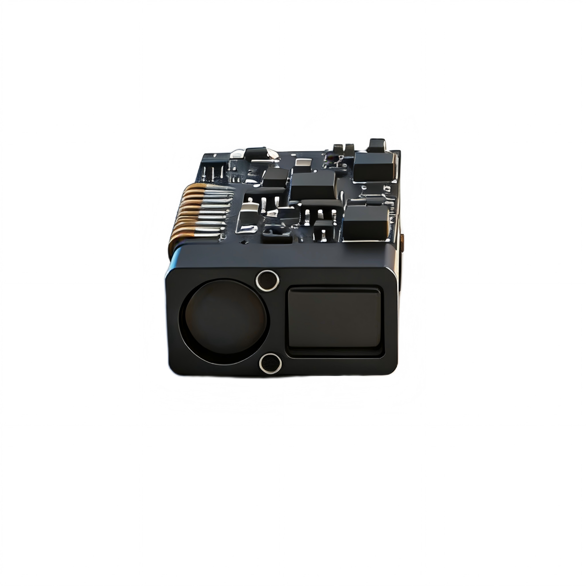
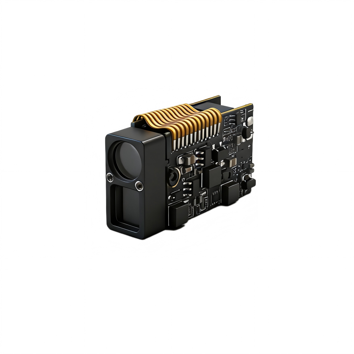
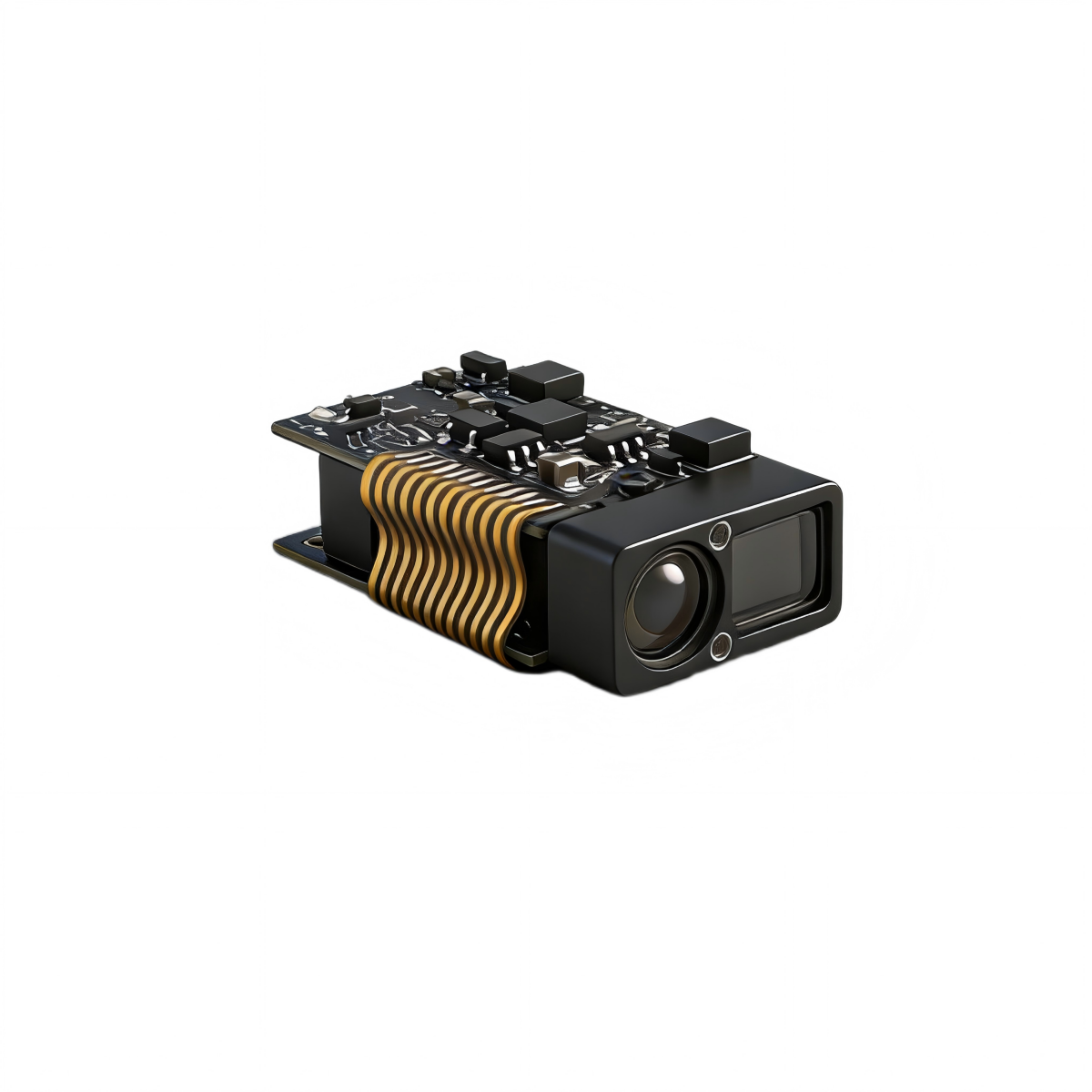
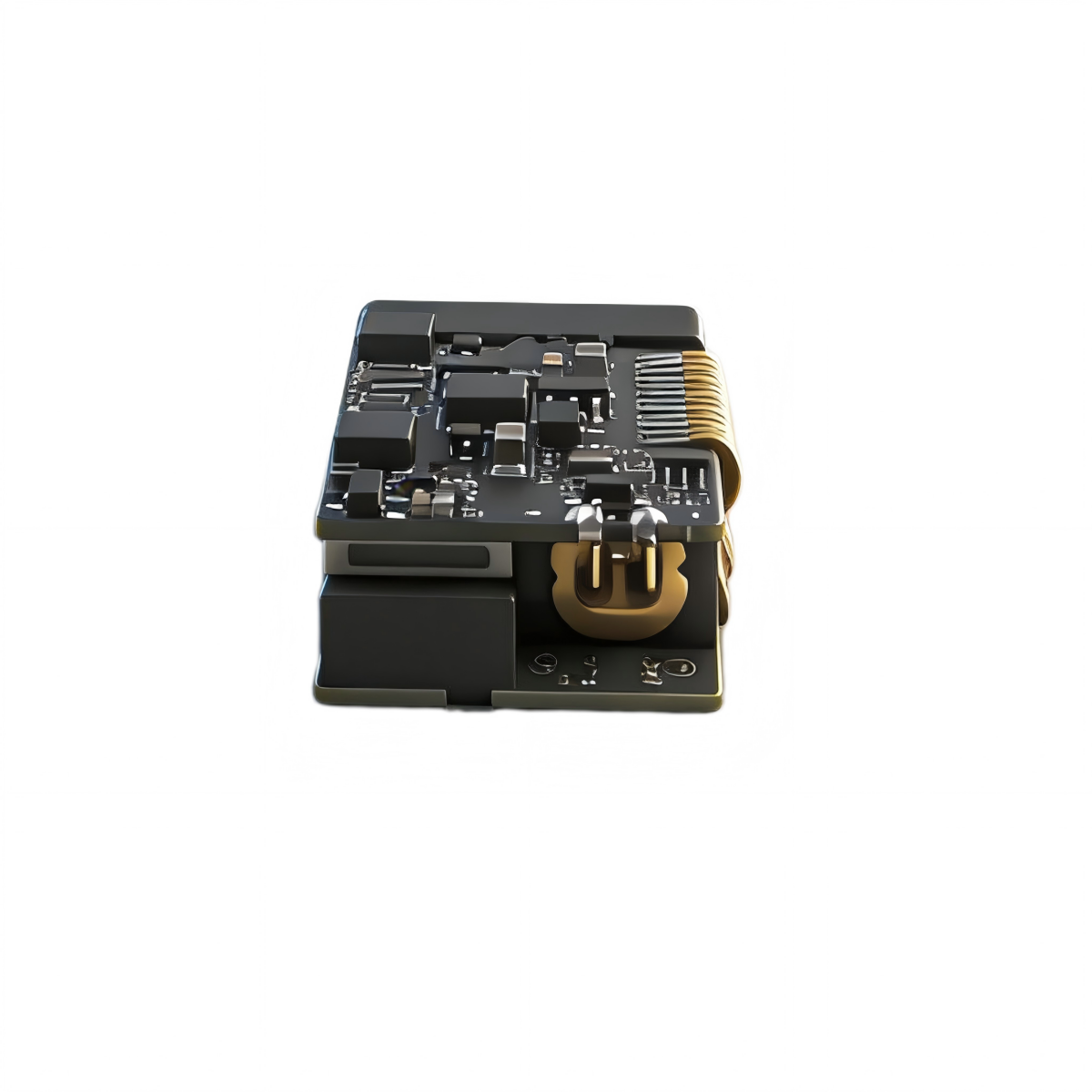
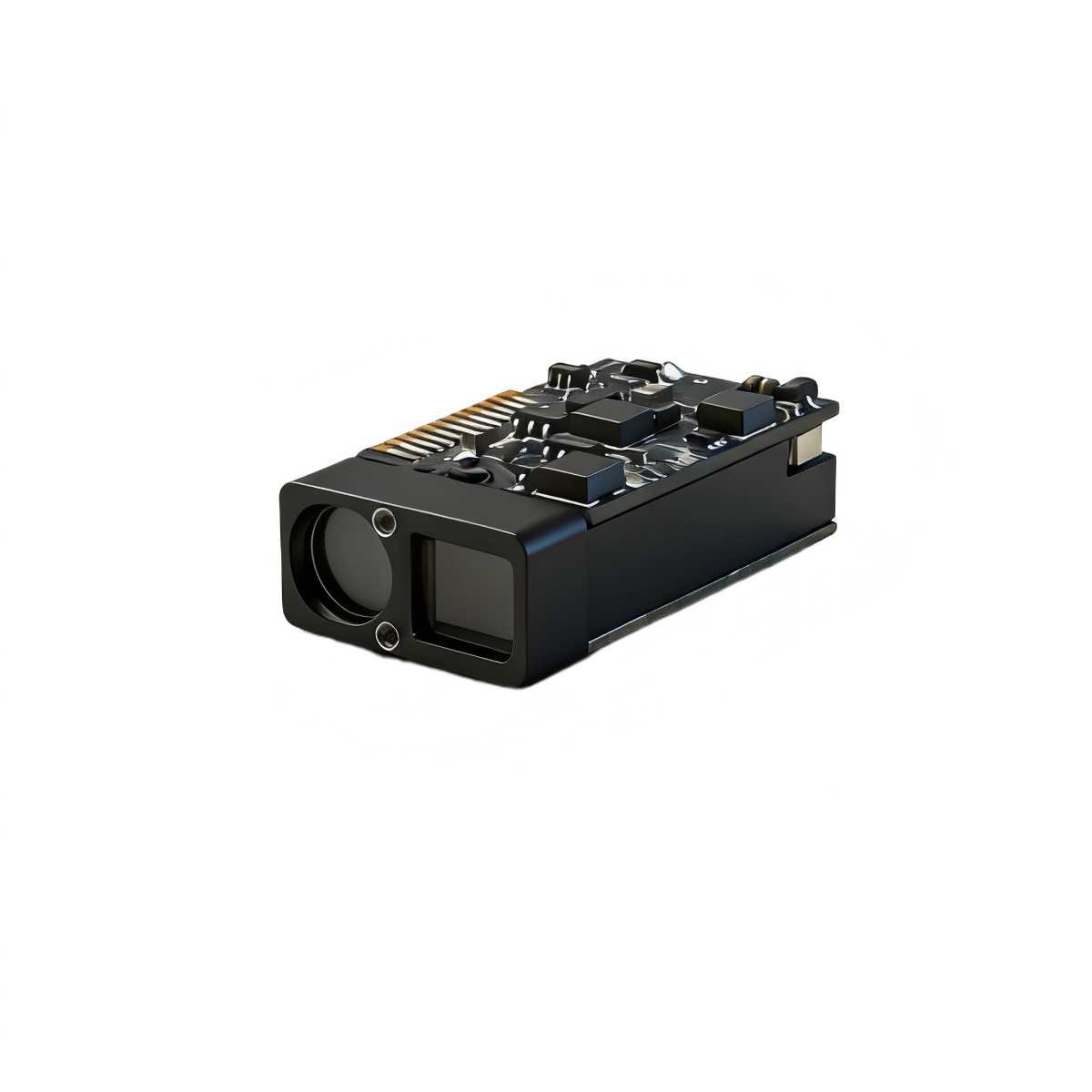
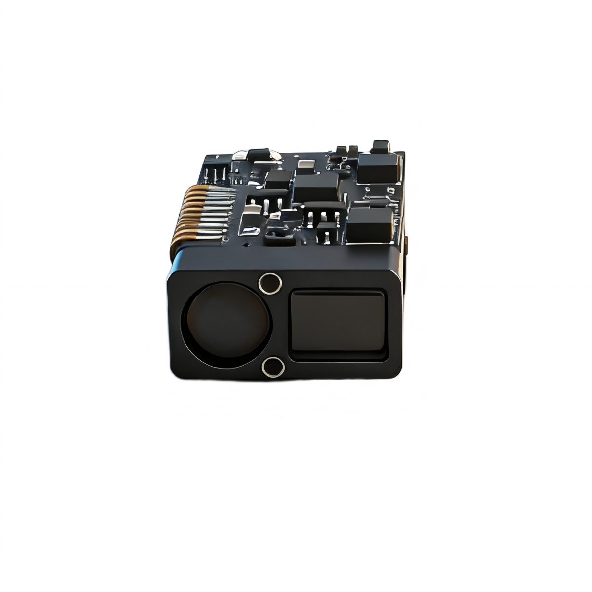
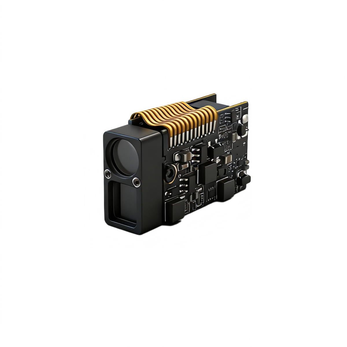
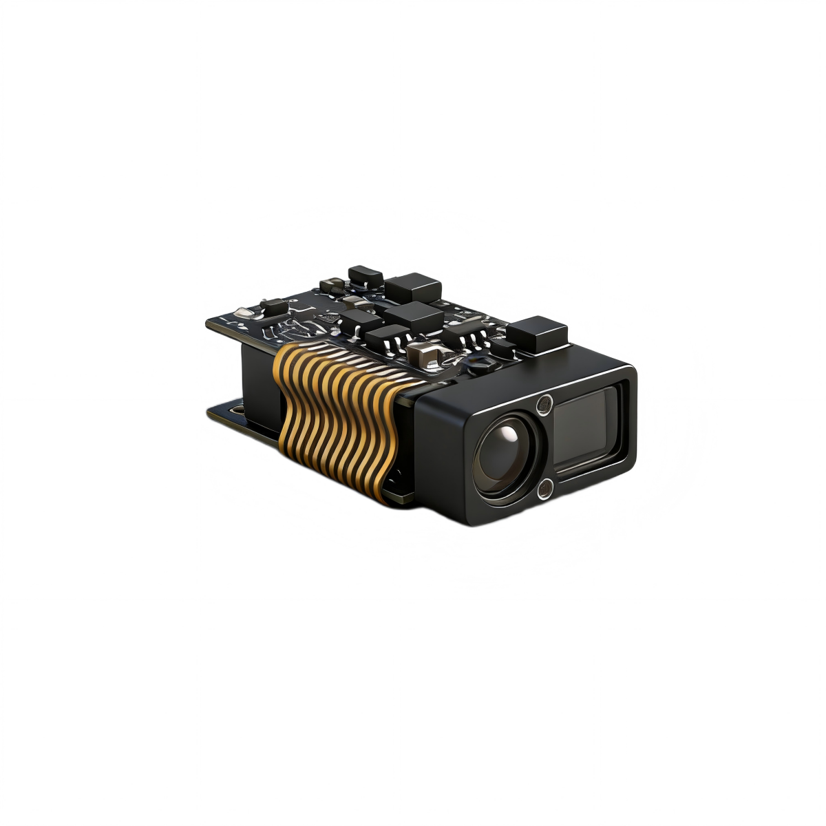
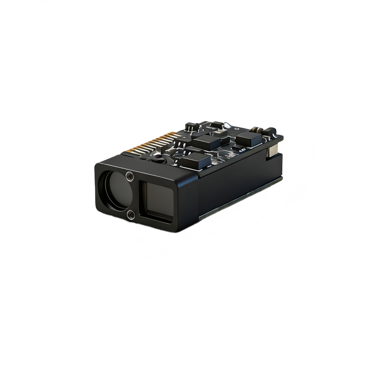
The SPD1200M2 is an ultra-compact 905nm laser rangefinder module developed for OEM integration in night vision devices, thermal imagers, telescopes, laser illuminators and lightweight civil UAV payloads. Compared with heavier 1km-class cylindrical modules, it is built around an ultra-slim rectangular format and a low-power UART-TTL interface, making it better suited to tightly packed electro-optical assemblies and miniature payload compartments.
The module operates at 905nm ±5nm and supports a measuring range of 0.2m to 1200m, with a maximum nighttime range up to 1500m. The specification states that strong sunlight and poor visibility can reduce effective range, which is normal for compact 905nm rangefinders. Ranging accuracy is ±0.3m below 100m, and ±0.3m + d×0.7‰ from 100m to 1200m, where d is the measured distance. The valid measurement rate is ≥98%, the false alarm rate is ≤1%, beam divergence is <4mrad, and the receiving aperture is 5.0mm × 7mm. Those figures position the SPD1200M2 as a miniature 905nm ranging core optimized for electro-optical integration rather than long-range industrial standoff use.
One of its strongest selling points is the 2–15Hz measuring frequency, with the manual also noting 4–15Hz adaptive operation as an option. The module supports both single measurement and continuous measurement. In single mode, when the target reflectivity is low, the system automatically repeats internal measurements until stable data is obtained, then sends the final result over the serial interface. In continuous mode, the typical refresh rate can be set to 2Hz, while the maximum reaches 15Hz. This gives designers more flexibility than the usual “slow single-shot only” 905nm module class.
Electrically, the SPD1200M2 uses a UART-TTL communication interface with a default baud rate of 115200bps, running from 3.3V to 5V. Startup time is ≤200ms, startup inrush current is about 380mA, average operating power is about 0.45W, and maximum power is ≤0.75W. That SWaP profile makes it attractive for battery-powered optics, compact sensor heads and small airborne payloads where every gram and watt gets audited like a suspicious expense report.
The protocol is intentionally simple. The sensor uses an 8-byte frame with 0x55 0xAA header bytes, a function code, four data bytes and checksum. Supported functions include single-shot ranging, continuous ranging, stop ranging, optional angle measurement for versions fitted with an angle sensor, power-on self-test, baud-rate configuration and LD constant-ON mode for development. The baud-rate menu supports 9600, 14400, 19200, 38400, 56000, 57600, 115200 and 230400bps, with changes taking effect after reboot. Distance data is returned in hexadecimal as the actual value multiplied by 10, so the host can reconstruct the range with one decimal place. The manual also warns not to keep LD constant-ON mode enabled for long periods.
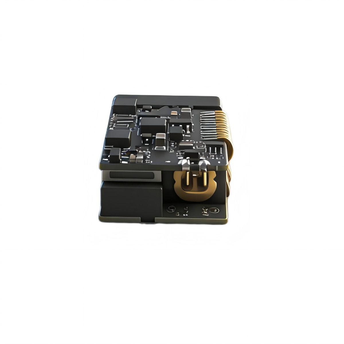
Mechanically, the SPD1200M2 is very small at 7.7mm × 15.3mm × 27.85mm and weighs ≤6g. It uses a 6-pin electrical interface with SW-SHOT, RXD, TXD, reserved I/O, VCC and GND. The manual notes that the Enable pin must be pulled LOW (connected to GND) during operation, which is one of those tiny details that saves a lot of muttering during bring-up. Because the body is slim and rectangular, it is easier to place inside narrow optical channels and compact housings than many older cylindrical 905nm modules.
The environmental envelope is practical for civil outdoor electronics: −20°C to +60°C operating temperature, −30°C to +70°C storage, IP67 protection inside the lens cavity, 1000g/ms shock resistance along the optical axis, 5–50–5Hz, 2.5g vibration resistance, and MTBF ≥1500h. These characteristics fit portable optics, embedded electro-optical heads and compact payloads used in outdoor monitoring and field instruments.
For front-window integration, the manual recommends H-K9L optical glass or fused silica, wedge-angle tolerance ≤3′, surface roughness around Ra 0.012, and an AR coating optimised for 855–955nm with transmittance ≥99.5%. After any hydrophobic or hard coatings, total transmittance should remain ≥98%. The guide also recommends keeping the optical-window thickness around 2–4mm, aligning the transmit optical axis parallel to the window normal, and keeping the air gap below 0.5mm to reduce extra loss and back-reflection. This is the sort of detail that quietly determines whether the shipped product behaves like the datasheet or like a small optical tragedy.
The use notes also make the real-world behaviour clear. Under the reference condition—a medium-reflectivity target such as a building wall, perpendicular incidence, clear weather and no direct sunlight—the module achieves nominal performance. The manual further notes representative target behaviour: high-reflectivity targets such as highway traffic signs, medium-reflectivity building walls, and low-reflectivity targets such as trees or animals all produce different maximum ranges, while rain, fog, snow and haze reduce usable distance. For long-distance measurement, tripod mounting is recommended.
Taken together, the SPD1200M2 is best understood as a micro 905nm ranging core for civil electro-optical integration: tiny enough for miniature optics, strong enough for 1200m-class daytime and 1500m-class nighttime performance, and simple enough for quick UART-based secondary development in night vision, thermal imaging, portable observation devices, civil UAV payloads and smart field equipment. Similar market offerings in the 905nm segment are also commonly framed around night vision, thermal imaging and UAV integration, which lines up neatly with this module’s actual niche.
_1445x.png?w=1200&h=1200&q=80)
_1800x.png?w=1200&h=1200&q=80)