
Product engineering brief
8 km 1535 nm OEM Laser Rangefinder for System Integration
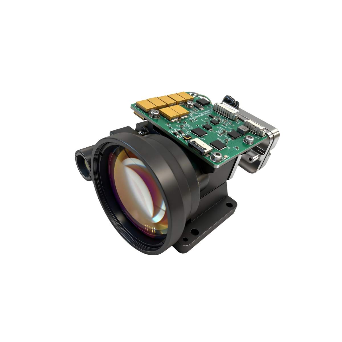
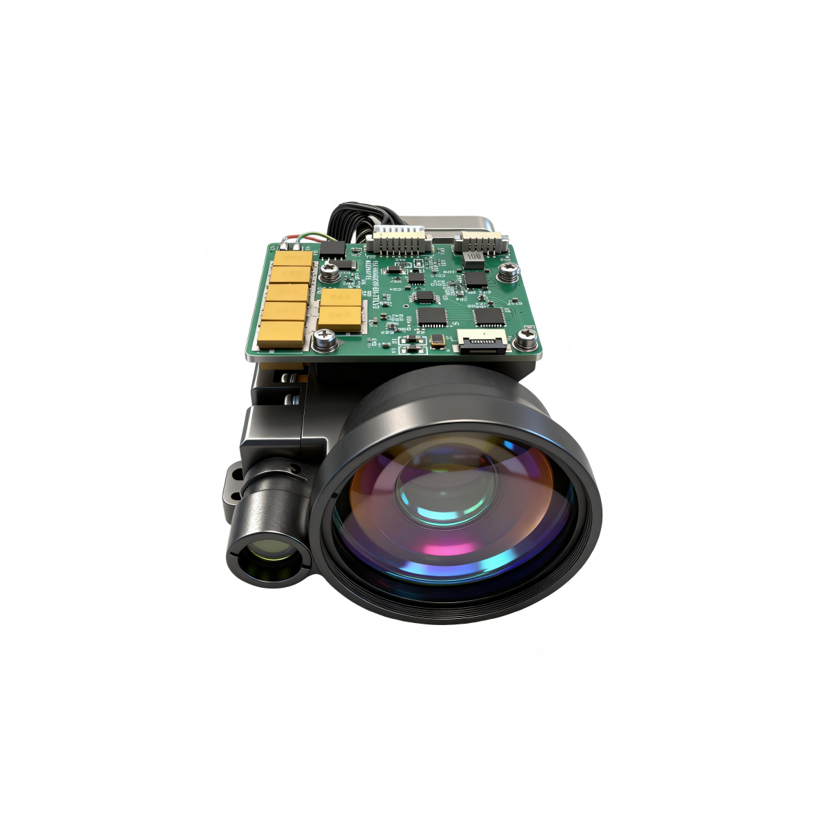
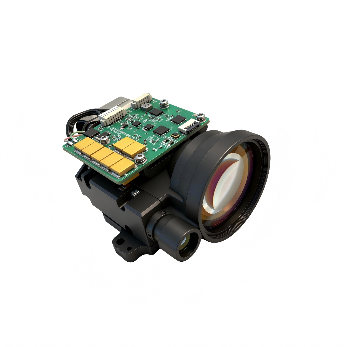
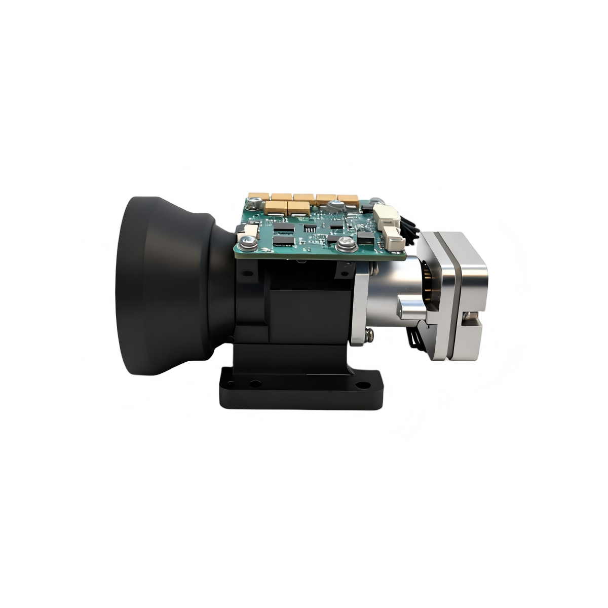
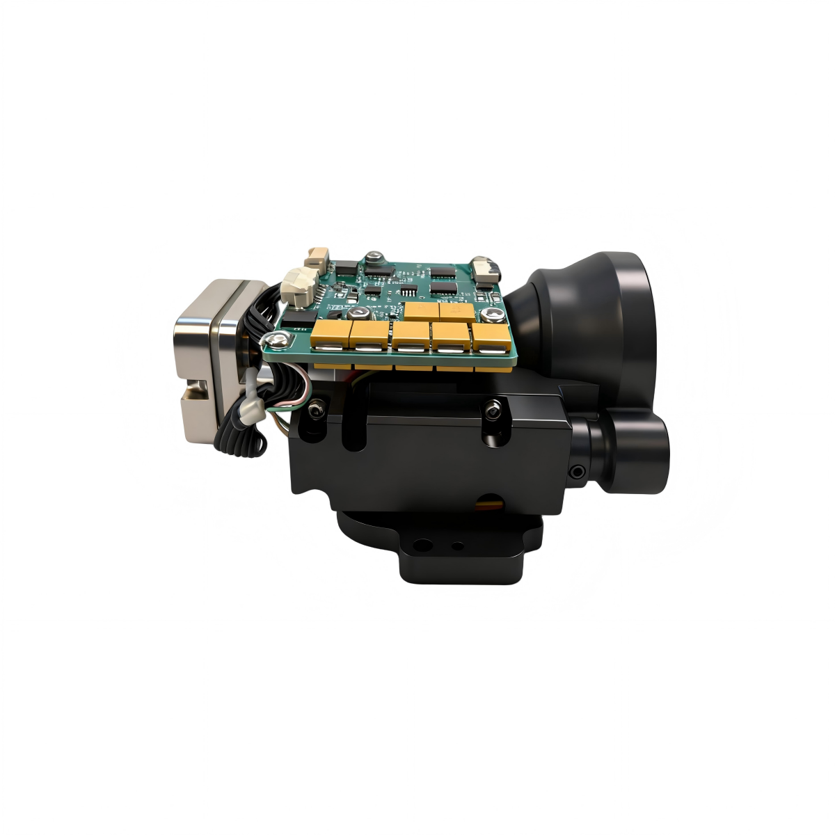
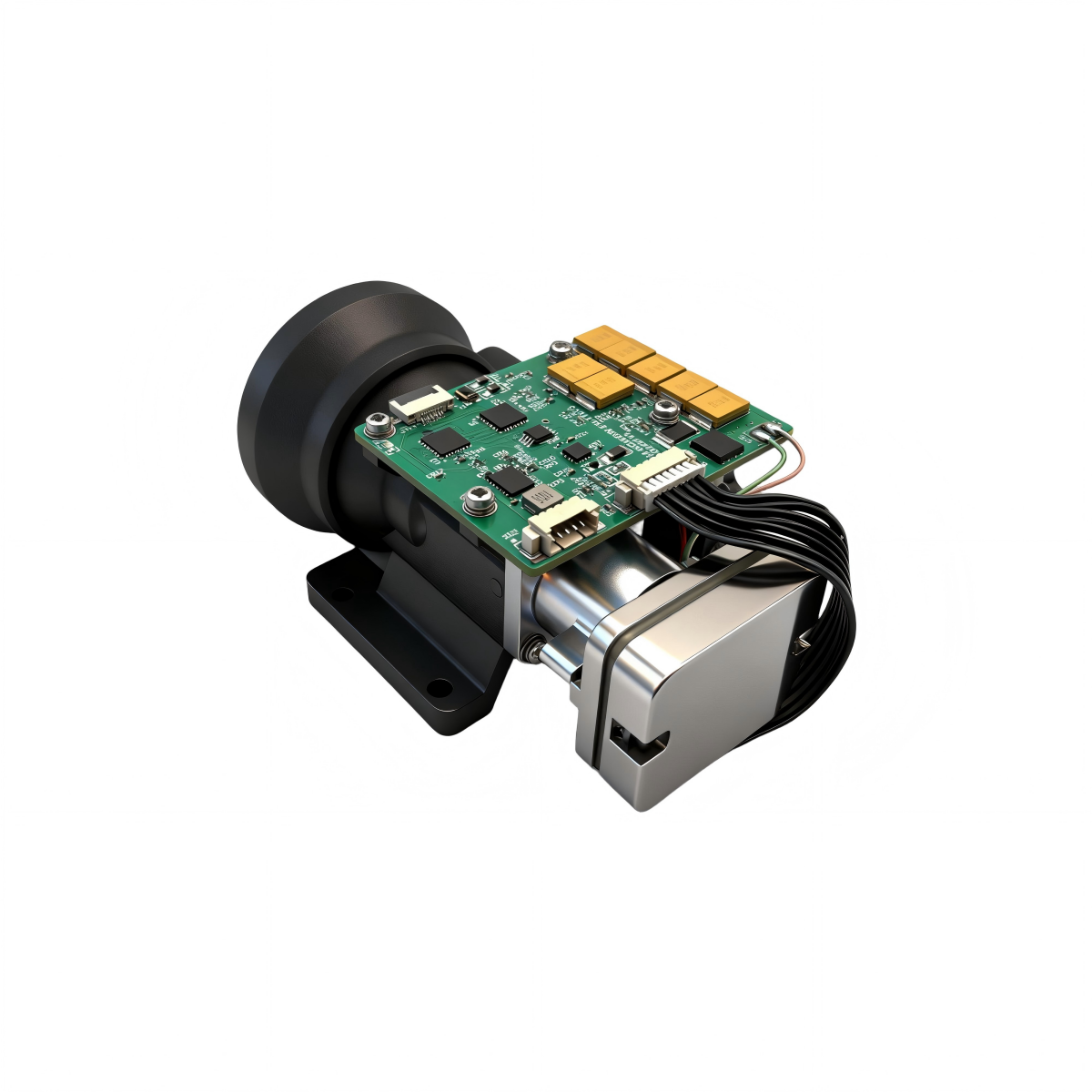
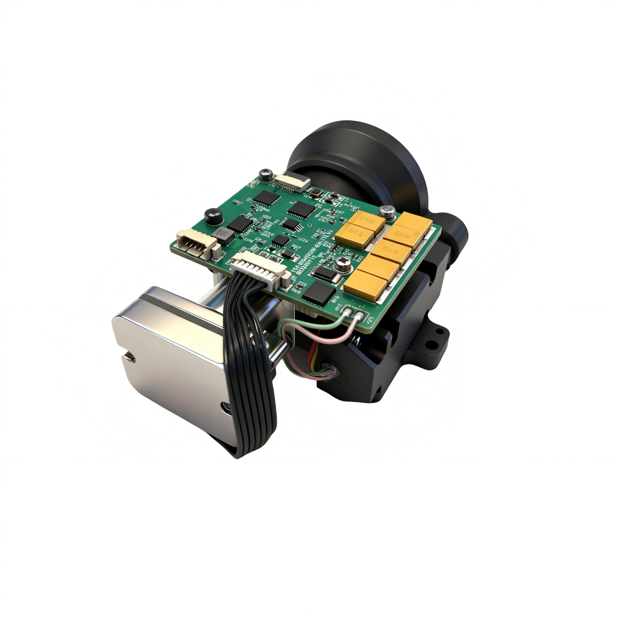
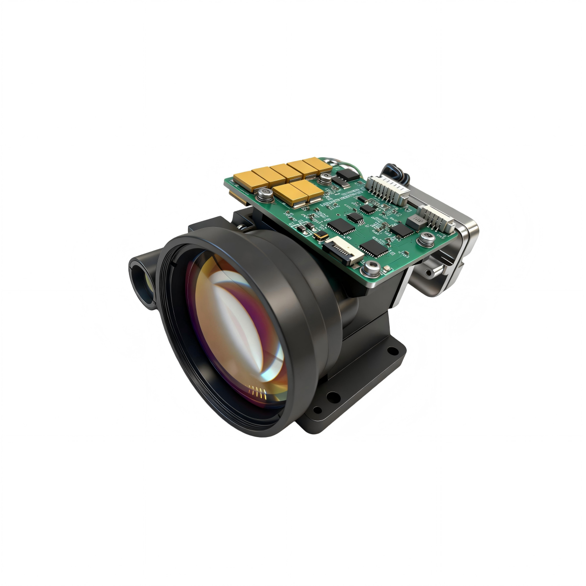
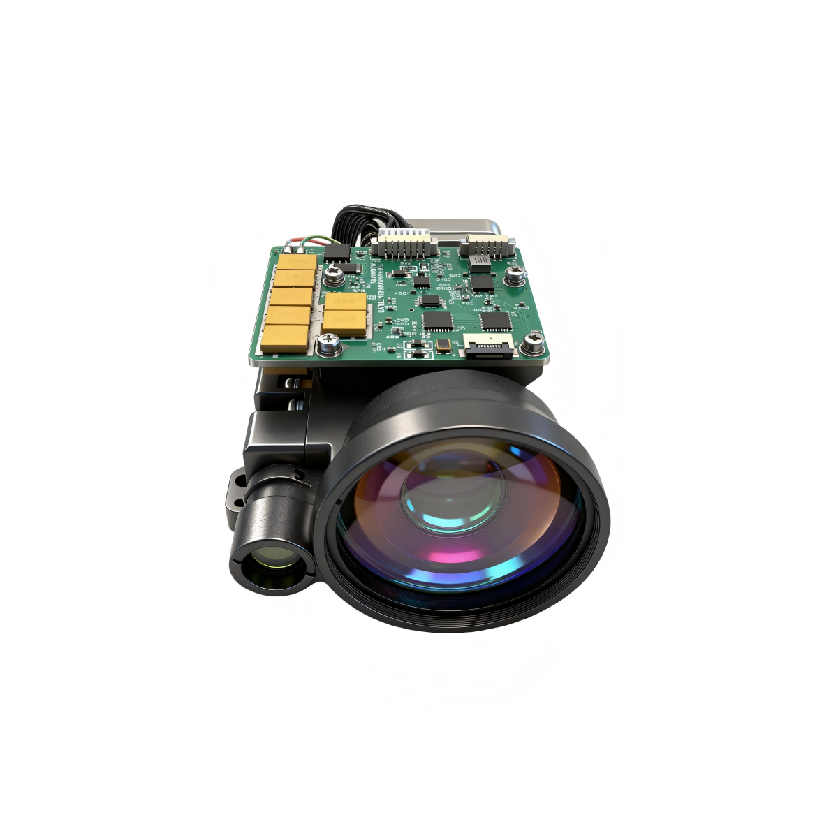
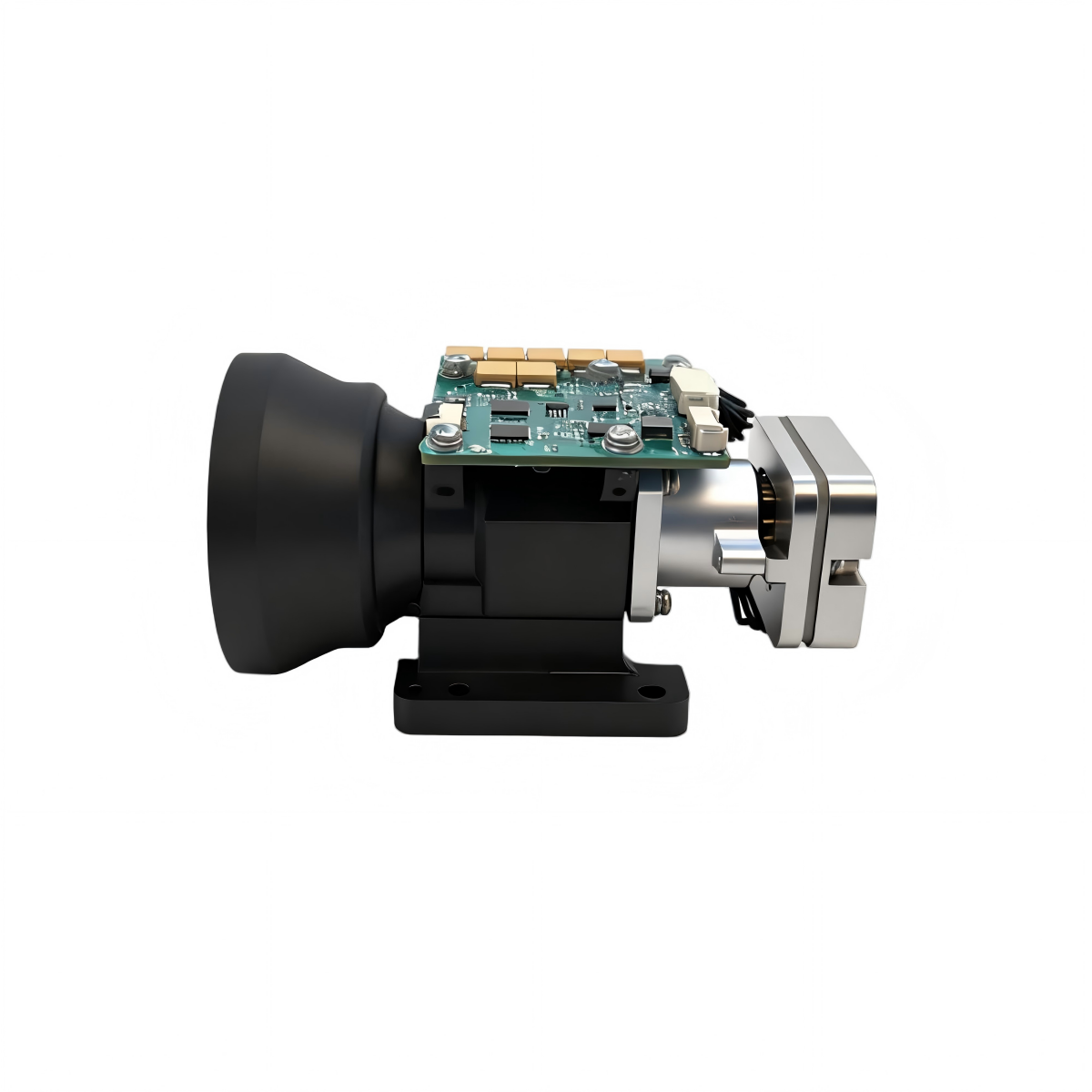
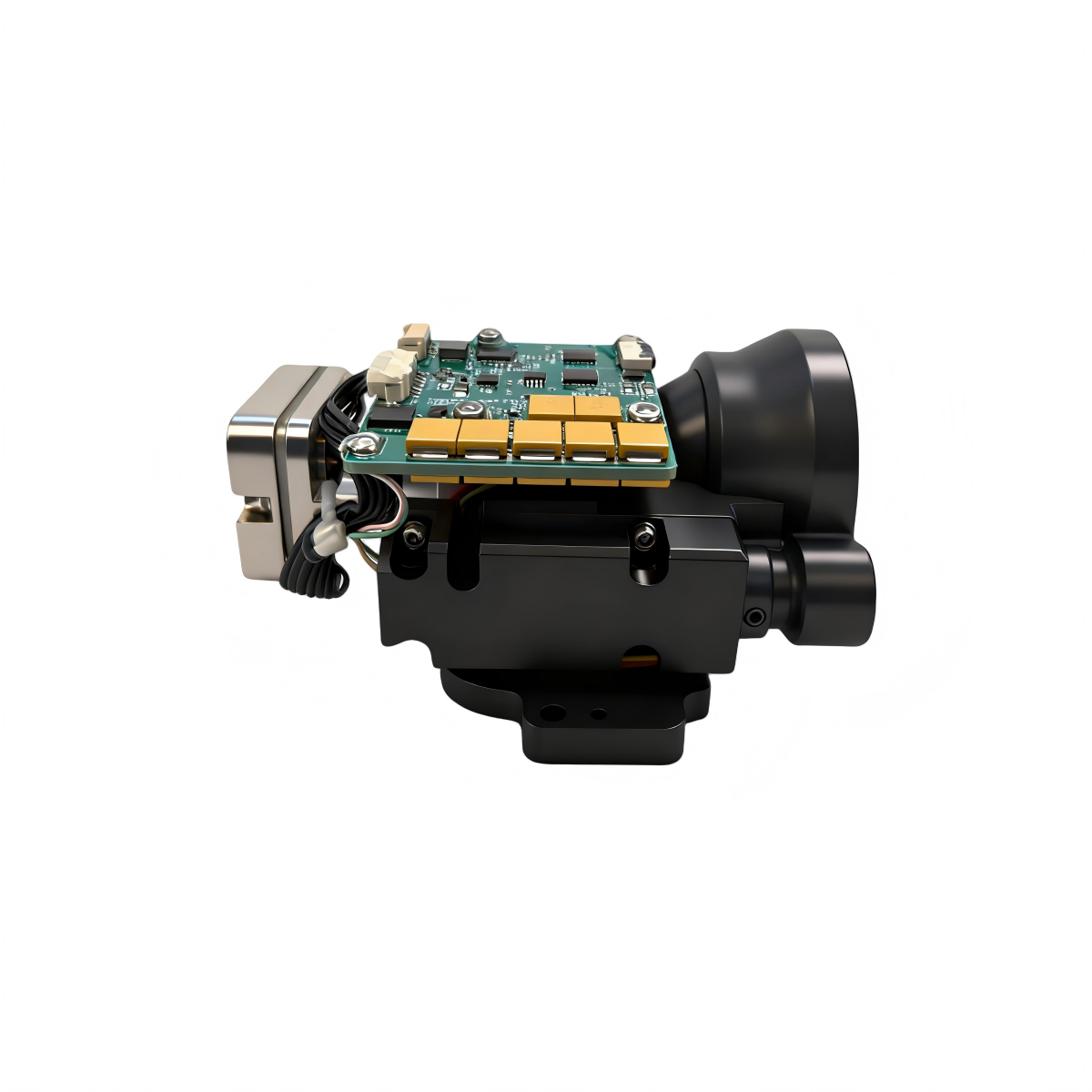
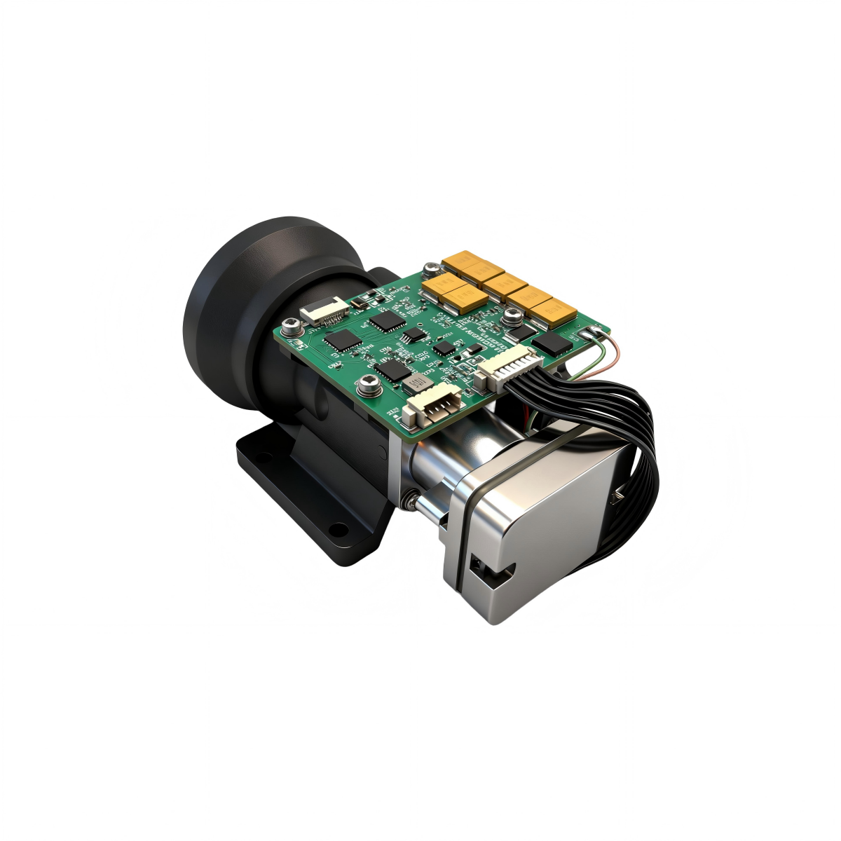
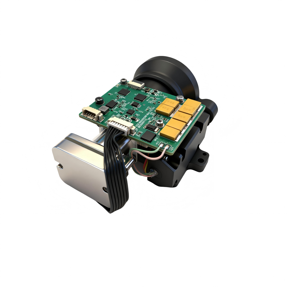
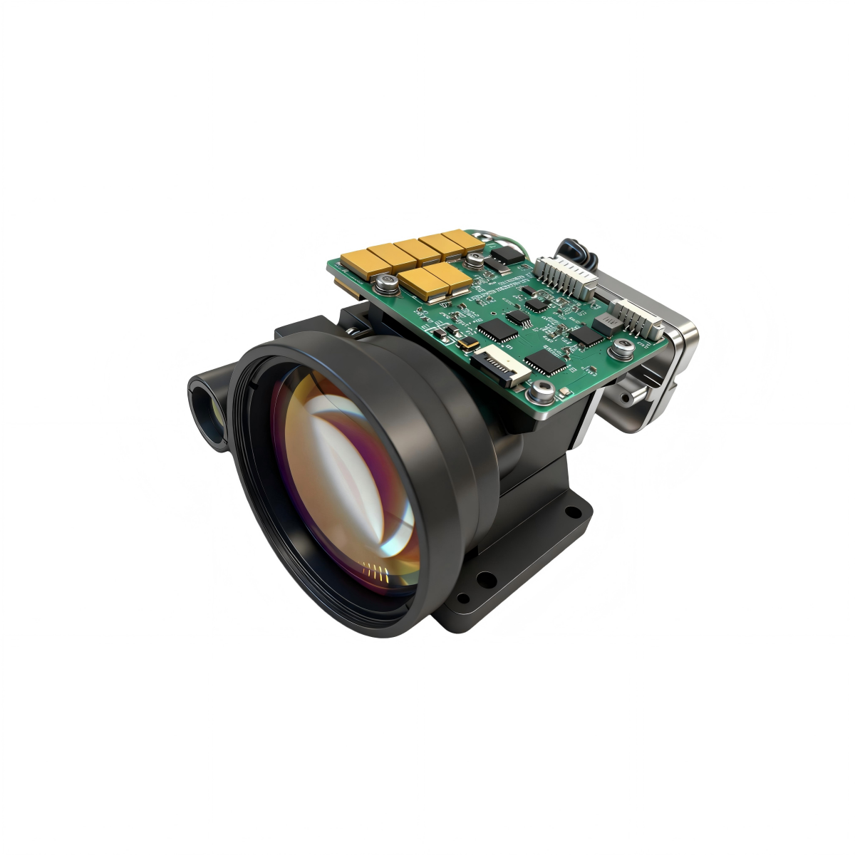
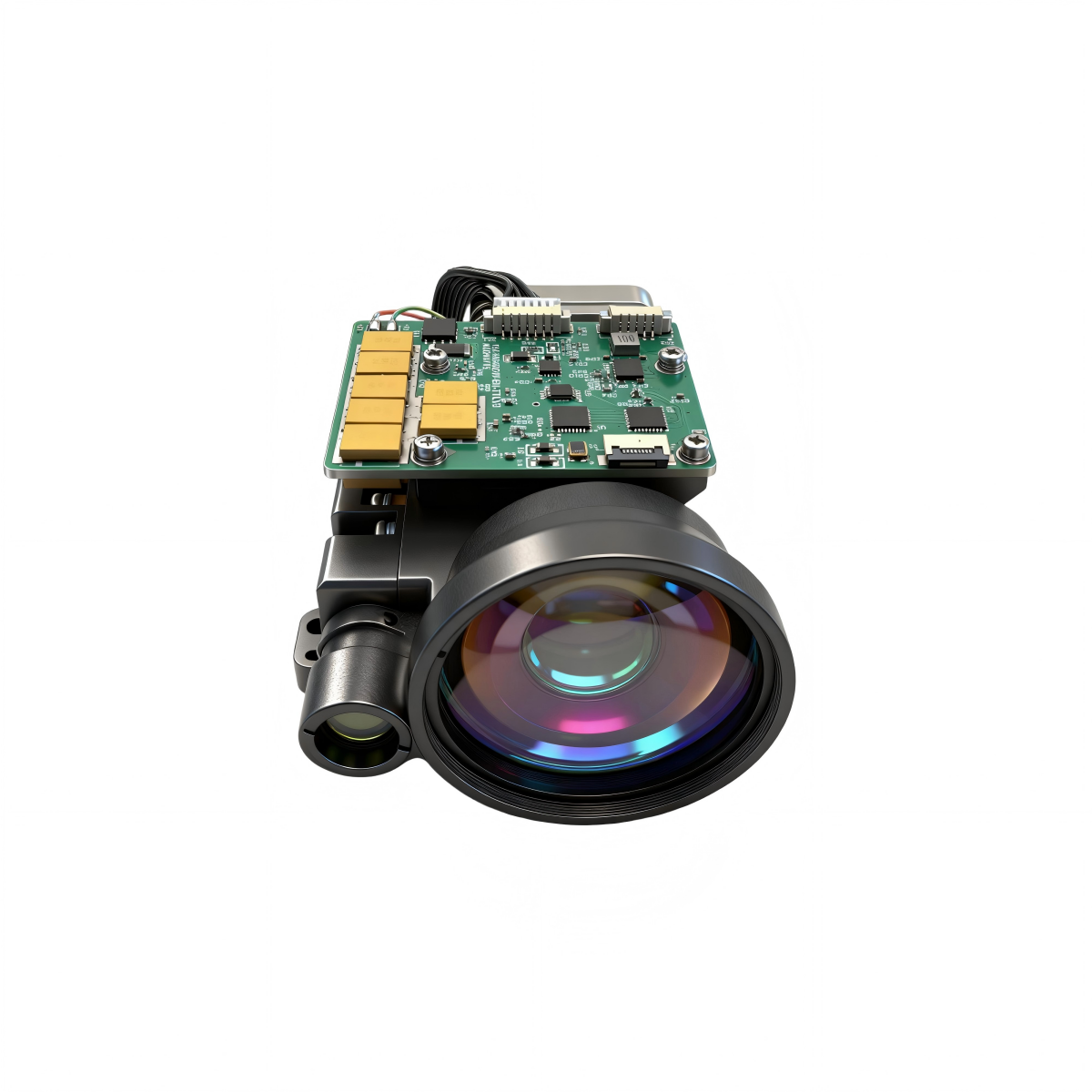
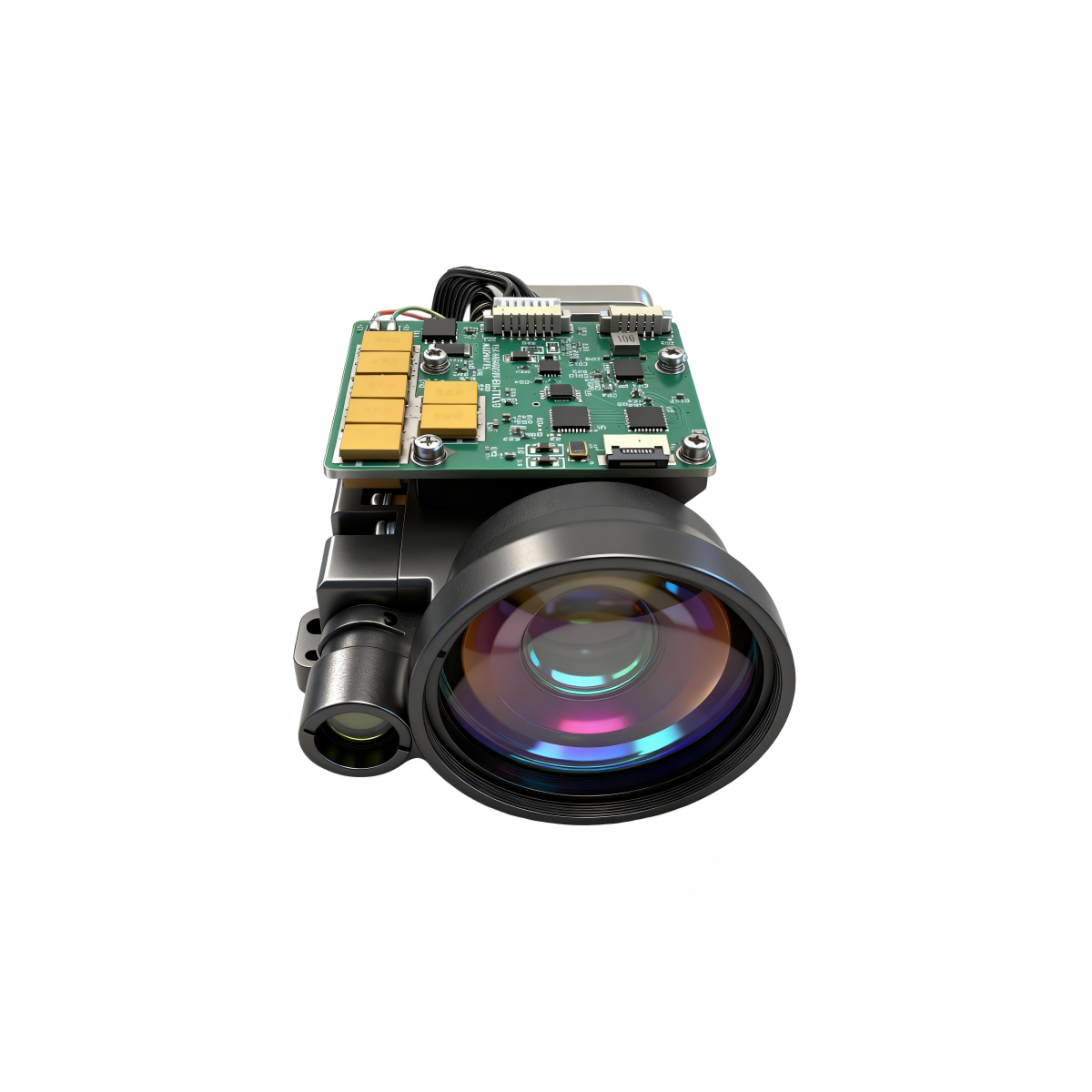
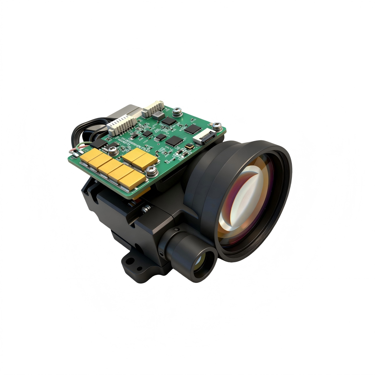
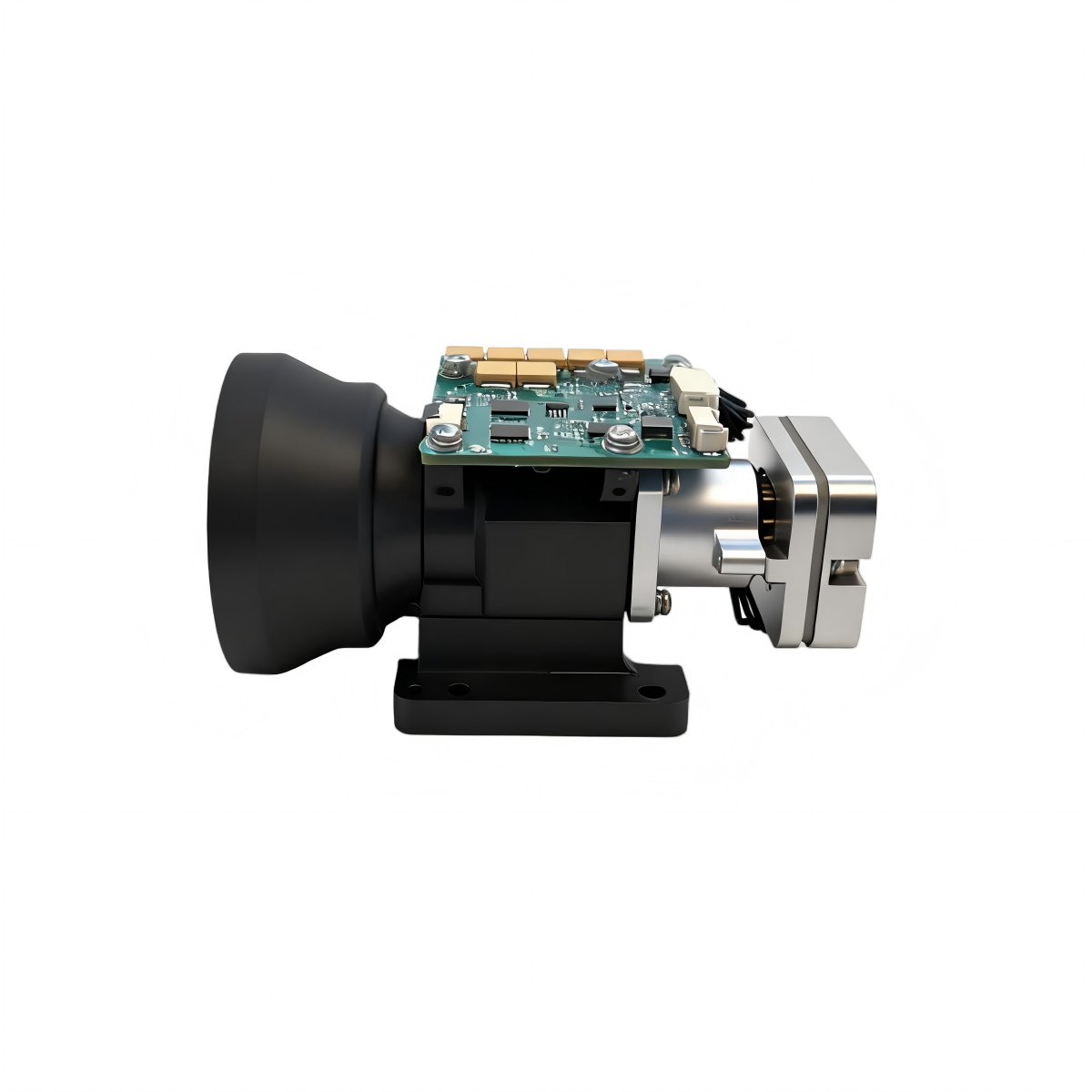
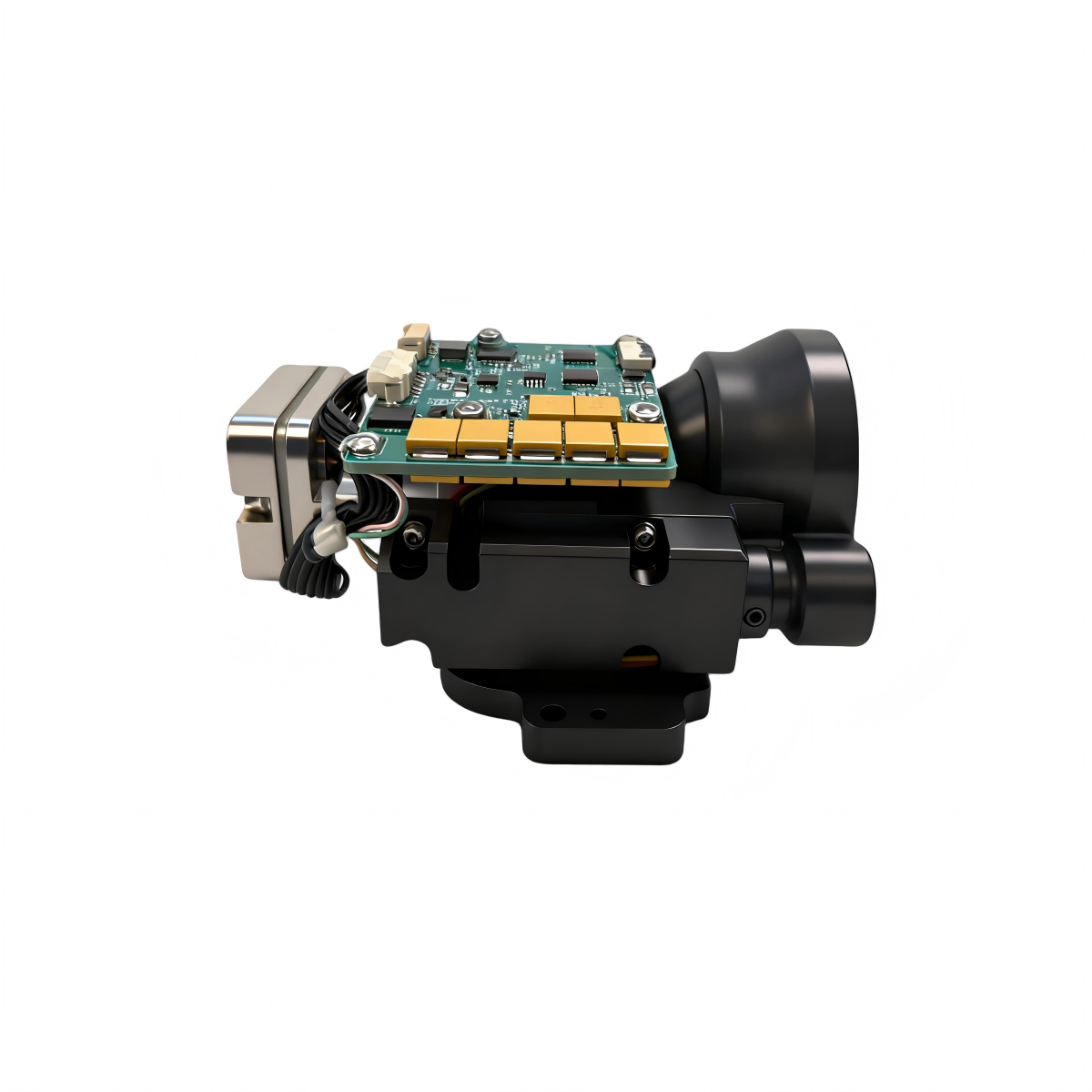
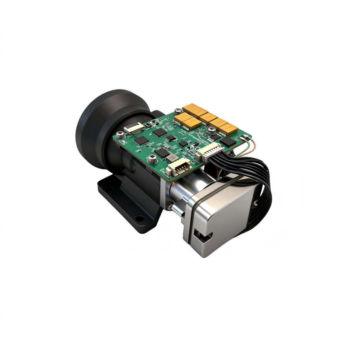
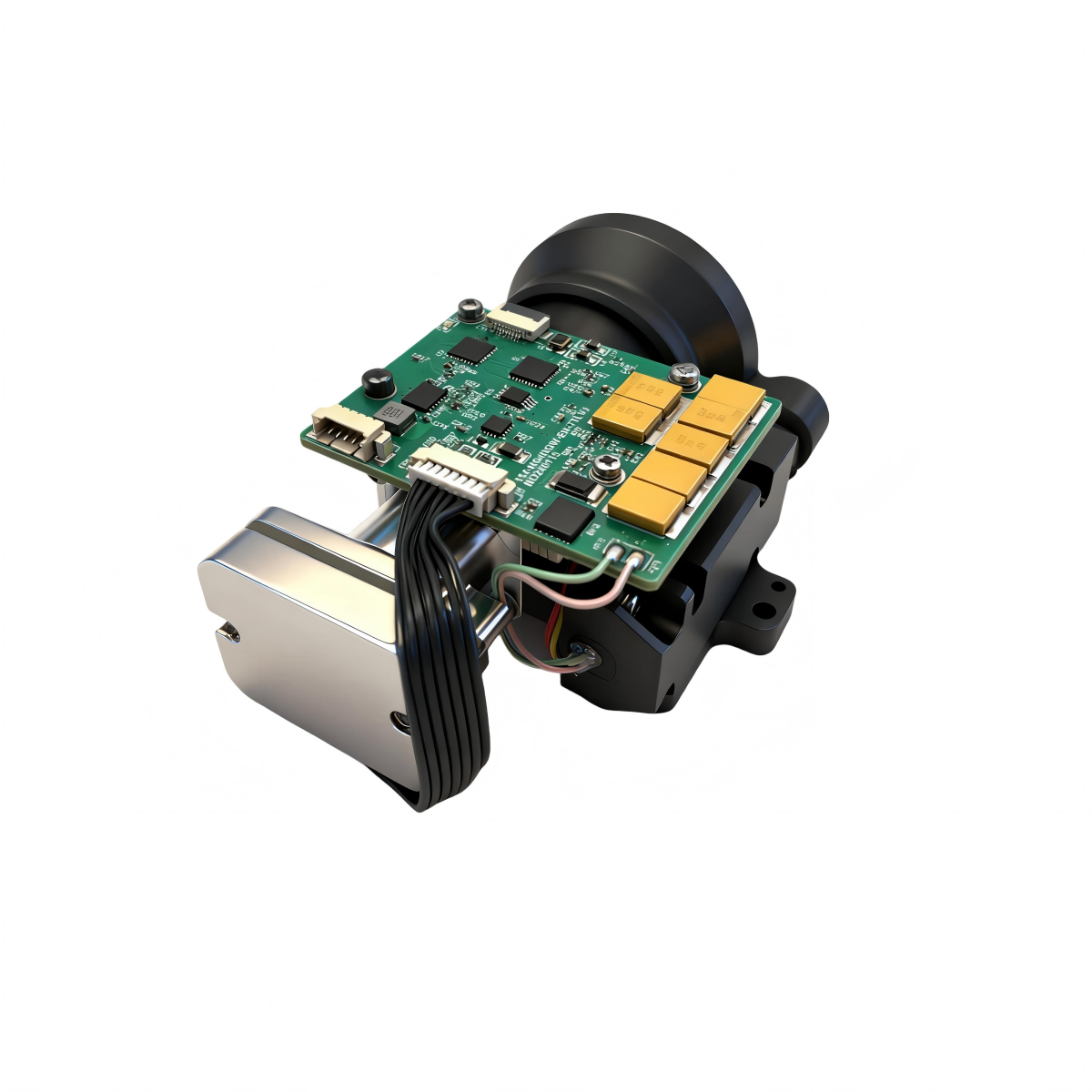
The ERDI LRF0815C is a board-level pulsed time-of-flight laser rangefinder module for engineers integrating long-range distance measurement into UAV gimbals, EO/IR payloads, handheld optics, reconnaissance systems, surveying instruments and fixed monitoring platforms. Its verified model specification combines a 15-8,000 m measurement envelope, up to three reported targets and selectable TTL or RS-422 communication in a 175 g maximum package.
- ≥8,000 m2.3 m x 2.3 m target, 30% reflectance, visibility ≥10 km
- 1535 ± 5 nmClass I rating stated in the module specification
- ±2 mRanging accuracy with ≤0.1 m reported resolution
- ≤175 g65 x 46 x 86 mm OEM board-level format
How it works
Pulsed Time-of-Flight Ranging
The LRF0815C emits a short 1535 nm optical pulse, collects reflected energy through its receiver aperture and measures the round-trip delay between transmission and the accepted echo.
For a direct time-of-flight system, target distance is derived from the propagation delay:
In the actual instrument, the receiver must distinguish the return pulse from solar background, detector noise and unwanted reflections. Range performance therefore depends on the complete link budget: transmitted pulse energy, beam divergence, target area and reflectance, atmospheric loss, receiver aperture, optical-filter transmission, detector sensitivity and the decision threshold used by the timing electronics.
The LRF0815C can report up to three targets. This is useful when several valid echo peaks occur along one line of sight, such as foliage before terrain or a vehicle before a building. The host should define which echo is operationally relevant instead of assuming that the first reported distance is always the intended target.
How 1535 nm compares with common alternatives
| Wavelength family | Engineering strengths | Integration considerations |
|---|---|---|
| 1535/1550 nm | Well suited to eye-safety-oriented long-range architectures; compatible with InGaAs-class receivers and narrowband filtering. | Detector and optical-component cost can be higher than silicon-based 905 nm systems. Final product classification must be verified after the module, window and controls are integrated. |
| 905 nm | Broad silicon detector ecosystem, compact components and cost-effective high-volume sensing. | Accessible-emission limits, detector dynamic range and solar-background rejection must be evaluated for the required range and final laser class. |
| 1064 nm | Common in high-energy ranging, designation and compatible electro-optical systems. | Not an automatic substitute for a 1535 nm eye-safety-oriented module; detector choice, coatings, safety controls and mission architecture differ. |
Wavelength alone does not determine fog performance or laser classification. Peer-reviewed fog measurements report only a small extinction-coefficient difference between 905 nm and 1550 nm at equal emitted power under the tested conditions; choose a wavelength from the complete safety, range, detector, atmosphere and cost trade space.
Core advantages
Designed Around OEM Integration Decisions
Each feature is tied to a system-level benefit that can be reviewed during platform design and validation.
Narrow-beam long-range architecture
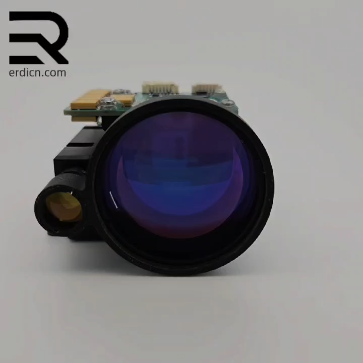
A minimum 300 µJ pulse-energy specification and ≤0.3 mrad divergence help concentrate transmitted energy, while the 40 mm receiver lens supports long-range return collection.
Multi-echo scene handling
Up to three reported targets gives the host more information in layered scenes. Selection logic can be matched to mapping, observation or tracking behavior.
Interface choice for different harnesses
TTL supports short internal connections in compact devices; differential RS-422 is better suited to longer cable runs and electrically noisy host platforms.
Controlled power budget
The stated ≤1.2 W standby, ≤2 W average and ≤3 W peak at 10 Hz figures help UAV and portable-system teams plan battery capacity, regulator headroom and thermal paths.
Wide operating-temperature specification
The -40 to +70 °C operating range supports outdoor and mobile platforms, subject to the host enclosure, thermal interface and project-specific qualification profile.
Open OEM mechanical format
The board-level construction gives integrators direct control of mounting, environmental sealing and the protective optical window, while making those design tasks part of final system responsibility.
Model-level data
Detailed LRF0815C Specifications
Values below are reorganized from the current ERDI model specification. Confirm the controlled datasheet revision, connector option and test profile with the quotation.
Basic Ranging Performance
| Model | LRF0815C |
|---|---|
| Specified measurement range | 15 to 8,000 m |
| Long-range test condition | ≥8,000 m to a 2.3 m x 2.3 m target, 30% reflectance, visibility ≥10 km |
| Minimum range | ≤15 m |
| Ranging accuracy | ±2 m |
| Reported range resolution | ≤0.1 m |
| Ranging frequency | 0.5 to 10 Hz |
| Multi-target reporting | Up to 3 targets |
| Precision rate / false-alarm rate | ≥98% / ≤1% under specified test conditions |
Optical Parameters
| Laser wavelength | 1535 ± 5 nm |
|---|---|
| Laser-safety rating | Class I stated in the LRF0815C module specification; the final integrated product requires its own safety assessment |
| Pulse energy | ≥300 µJ |
| Beam divergence | ≤0.3 mrad |
| Transmitter lens diameter | Φ12 mm |
| Receiver lens diameter | Φ40 mm |
Electrical and Communication Interface
| Supply voltage | 12 V DC |
|---|---|
| Communication option | RS-422; TTL optional |
| TTL connector | Molex 51021-0500, 3.3 V RX/TX, CTRL, +12 V and GND |
| RS-422 connector | J30J with RX+/RX-, TX+/TX- and power/ground contacts; mate and cable supplied per order configuration |
| Serial format | 115200 bps, 8 data bits, 1 stop bit, no parity (8N1) |
| Standby power | ≤1.2 W |
| Average power | ≤2 W |
| Peak power | ≤3 W at 10 Hz |
| Molex pin | Signal | Function |
|---|---|---|
| 1 | TTL RX | 3.3 V serial input to the rangefinder |
| 2 | TTL TX | 3.3 V serial output from the rangefinder |
| 3 | CTRL | 3.3-5 V power on; 0 V power off |
| 4 | +12 V | Positive supply input |
| 5 | GND | Supply return |
Harness caution: The legacy J30J table contains a label inconsistent with the stated 12 V supply. Use the controlled interface drawing supplied with the ordered connector option before applying power; do not build a harness from a marketing-page pin label alone.
Mechanical and Environmental
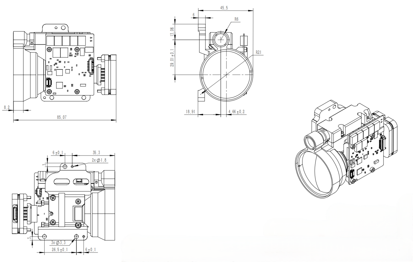
| Dimensions (L x W x H) | 65 x 46 x 86 mm |
|---|---|
| Weight | ≤175 g |
| Operating temperature | -40 to +70 °C |
| Storage temperature | -55 to +75 °C |
| Impact resistance | Specified to meet MIL-STD-810G testing; confirm method, severity and acceptance criteria for the order |
| Vibration resistance | Specified to meet MIL-STD-810G testing; confirm method, severity and mounting condition for the order |
Need an interface and fit review?
Send the host voltage, connector preference, cable length, available envelope, target definition and environmental profile. ERDI can confirm the correct revision before purchase.
Application engineering
Where the LRF0815C Fits
The module is intended for integration, so optical, electrical, mechanical and software interfaces must be validated as one system.
UAV gimbals and EO/IR payloads
Use long-range distance data for geolocation, observation and sensor cueing. Review payload mass, regulator transient response, boresight stability and vibration before flight qualification.
Surveying and mobile mapping
Integrate measured range with attitude and position data. Calibrate the lever arm, timing latency and boresight between the rangefinder and navigation sensors.
Handheld and portable optics
Plan the battery, user controls, protective window and thermal path around the selected repetition rate. Reassess accessible emission for the finished enclosure.
Fixed monitoring and reconnaissance
RS-422 can support robust internal cabling in larger installations. Validate grounding, surge behavior, weather sealing, window contamination and expected target reflectance.
Protective-window integration
A host window becomes part of both the transmit and receive paths. Use coatings designed for the 1525-1545 nm band, control wedge and surface quality, and keep ghost reflections away from the receiver timing gate. The current integration guidance targets at least 99% window transmission and at least 97% complete-system transmission; confirm these values for the selected coating stack and incidence angle.
After enclosure assembly, repeat boresight, minimum-range, false-alarm and maximum-range checks. A clean bench result before the window is installed is not a substitute for finished-platform validation.
Technical FAQ
Questions System Integrators Ask
Does the 8 km specification apply to every target?
No. It is specified for a 2.3 m x 2.3 m target with 30% reflectance and visibility of at least 10 km. Smaller, darker, oblique or obscured targets and degraded weather can reduce achievable range.
Is the final product automatically Class I after integration?
No. The LRF0815C specification states Class I for the module, but IEC 60825-1 treats the accessible emission of the finished product as a system-level responsibility. The host window, control logic, service access and failure conditions must be included in the final safety assessment.
When should I choose TTL instead of RS-422?
TTL is typically appropriate for short internal connections with a shared ground and controlled noise. RS-422 is preferred for longer harnesses or platforms with stronger electromagnetic interference because it uses differential signaling. Confirm connector, pinout and cable configuration before release.
Why can the module report three targets?
A transmitted pulse may produce several accepted return peaks from objects at different distances. The module can report up to three targets so the host can select the echo appropriate to its operating logic. Field scenes should be tested to tune that selection.
What information should be included in a technical inquiry?
Provide the target size and reflectance, required minimum and maximum range, visibility or weather assumptions, update rate, connector and cable length, available volume and mass, supply limits, operating temperature, host window details and expected annual quantity.
Engineering references
- H. N. Burns, C. G. Christodoulou and G. D. Boreman, "System Design of a Pulsed Laser Rangefinder," Optical Engineering, 30(3), 1991.
- H. Ma et al., "The Short-Range, High-Accuracy Compact Pulsed Laser Ranging System," Sensors, 22(6), 2146, 2022.
- P. Duthon, M. Colomb and F. Bernardin, "Light Transmission in Fog: The Influence of Wavelength on the Extinction Coefficient," Applied Sciences, 9(14), 2843, 2019.
- IEC 60825-1, Safety of laser products - Part 1: Equipment classification and requirements.
References provide general engineering context. LRF0815C purchase specifications, interface documents and acceptance criteria are controlled by the ERDI document revision supplied with the order.
Technical resources
Download LRF0815C Product Data
Use the product brief for early-stage comparison. Request the controlled datasheet, interface protocol and mechanical file before design release or purchase.
LRF0815C Product Brief
Model specifications, integration notes, test-condition definitions and engineering references in PDF format.
Download Product Brief (PDF)Controlled Integration Package
Request the current datasheet revision, serial protocol, connector drawing and mechanical file for your selected configuration.
Request Technical FilesStart the engineering review
Discuss Your LRF0815C Integration
Share your platform envelope, target definition, interface, environment and quantity. ERDI will help verify the configuration and documents required for evaluation.