
Distance-measuring sensor modules give an automation controller a direct measurement of the space between the sensor and a target. Laser time-of-flight modules are useful when the platform needs a narrow field of view, fast updates and a compact optical package. Selection still depends on the target, operating environment, interface and system-level safety requirements.
How a laser distance sensor measures range
A pulsed laser rangefinder sends a short optical pulse and records the time required for the reflected signal to return. The controller converts the round-trip time into distance. Receiver thresholds, range gates and target-selection logic help separate a valid return from detector noise, sunlight, atmospheric backscatter and foreground objects.
Automation software should treat the reported range together with status flags, target count and timeout information. A single number without validity data is not sufficient for motion control or fault handling.
Verified LRF0105C configuration
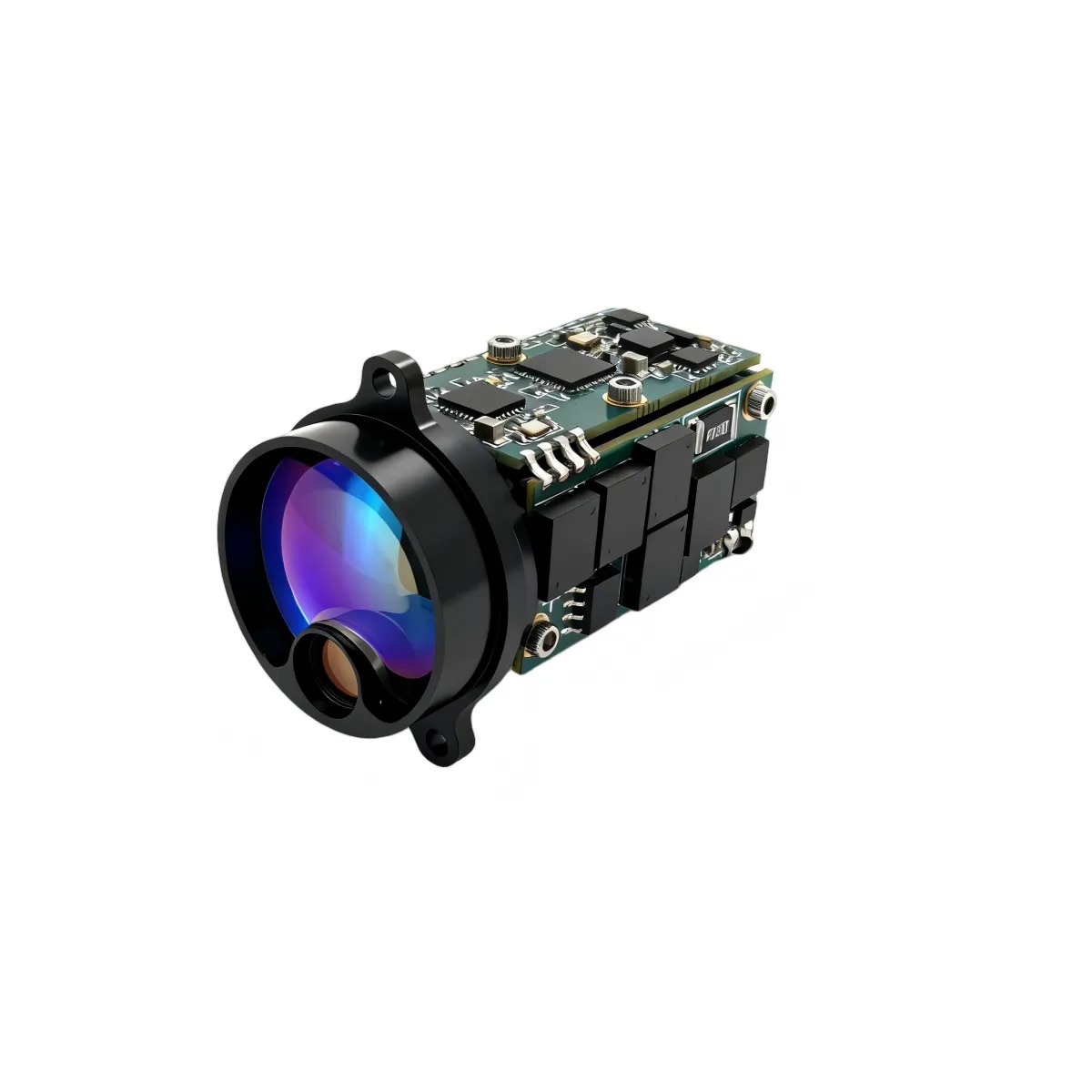
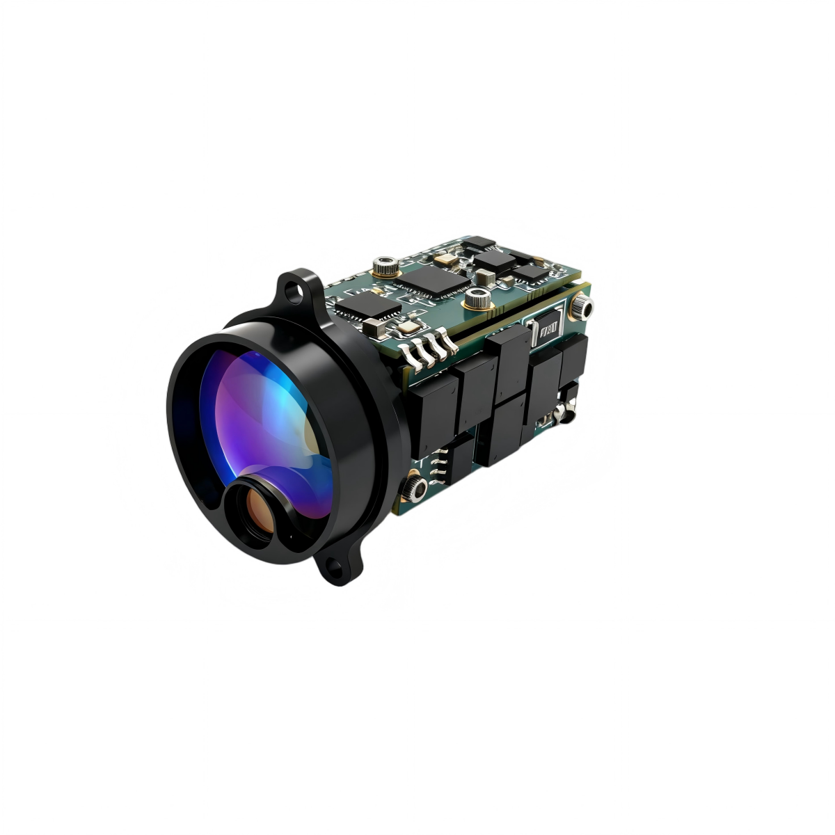
The LRF0105C is one example of a compact module intended for UAV gimbals, handheld optics, robotic sensors and embedded measurement systems. The current product page publishes the following configuration.
| Parameter | Published specification |
|---|---|
| Wavelength | 1535 ± 5 nm |
| Beam divergence | ≤ 1 mrad |
| Minimum range | ≤ 15 m |
| Ranging frequency | Single-shot, 1 Hz, 5 Hz and 10 Hz |
| Targets reported | Up to 3 |
| Ranging accuracy | ± 2 m |
| Range resolution | ≤ 0.1 m |
| Supply and interface | 3-5 V DC and 3.3 V TTL serial control |
| Power | ≤ 1 mW standby, ≤ 0.8 W average and ≤ 1.5 W peak |
| Envelope and mass | 34 mm diameter x 47.5 mm; ≤ 29 ± 1 g |
| Operating temperature | -40 to +70 degrees C |
Published range values are target-dependent. Under the stated visibility and reflectivity conditions, the product page lists at least 4,000 m for a 60% reflective building target, 3,000 m for a 2.3 x 2.3 m target at 30% reflectivity, 1,500 m for a 0.5 x 1.7 m target and 800 m for a 0.2 x 0.3 m target. Integrators should reproduce the relevant target and visibility conditions during platform testing.
Where the module fits in an automated system
- Robotics: range confirmation, object detection and approach control when the required field of view and update rate match the module.
- UAV and EO/IR payloads: target range data for a gimbal controller, mapping workflow or sensor-fusion system.
- Handheld and fixed optics: distance measurement for observation, inspection and alignment tasks.
- Industrial equipment: position or clearance measurement after the target surface and environmental limits have been validated.
A ranging module is not automatically a safety-rated presence sensor. Machine guarding and personnel-protection functions require components and architectures certified for that purpose.
OEM integration checklist
- Mechanical: define mounting datums, clear aperture, boresight alignment, cable routing and contamination control.
- Electrical: confirm the 3-5 V supply, peak-current margin, grounding, low-power control and startup sequence.
- Interface: document baud rate, packet format, command timing, checksums, target-selection mode and error responses.
- Thermal: verify the duty cycle and heat path across the intended operating temperature.
- Control logic: set limits for stale data, missed returns, impossible jumps and multi-target handling.
Measurement validation
Practical range depends on target size, reflectivity, angle, visibility, solar background, window transmission, vibration and pointing stability. Qualification should include minimum and maximum range, accuracy, repeatability, false returns, multiple targets, temperature, vibration, electromagnetic compatibility and boresight retention.
The product page lists a module-level Class I eye-safety classification. The enclosure, optics, operating mode and accessible emission of the finished system still require an appropriate laser-safety assessment and the necessary labels, interlocks and operating procedures.
Product information
See the current LRF0105C 1535 nm laser rangefinder module product page for the latest specifications, interface details and product media. Contact ERDI TECH LTD for datasheets, protocol documents and OEM integration support.