
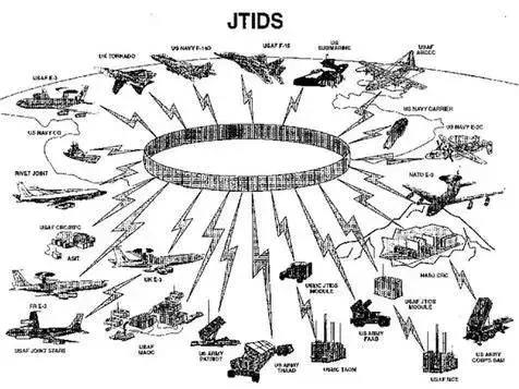
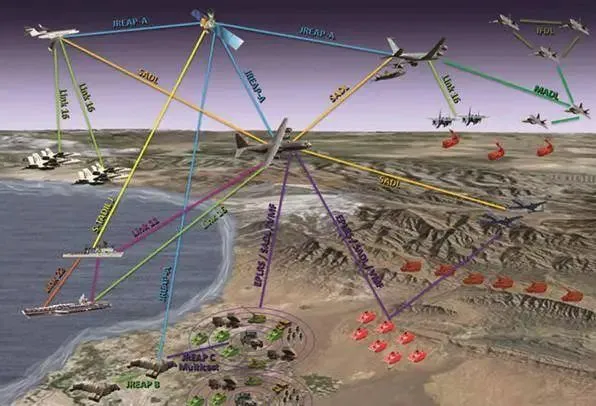
Data Link-16 is used to exchange real-time tactical data between combat forces. Compared to Link-11 and Link-4A, significant improvements have been made in the system, such as no core node, anti-jamming, communication flexibility, separation of transmission and data security, increasing the number of participants, increasing data capacity, network navigation features, and secure voice. Link-16 utilizes the Joint Tactical Information Distribution System (JTIDS), which includes two types of terminal software, hardware, radio frequency equipment, and the resulting high-capacity, secure, anti-jamming waveform. The basic version of JTIDS employs Time Division Multiple Access (TDMA), and the signal is a spread spectrum signal. Two spread spectrum methods are used in TDMA: direct sequence spread spectrum and frequency hopping. Each time slot of JTIDS TDMA emits 129 pulses, with the first 20 being the synchronization segment and the remaining 109 being the data segment.
In the synchronization segment and data segment, the pseudorandom sequence segments used as pulse modulation signals are different. The pseudorandom sequence segments selected for the synchronization segment can be pseudorandomly selected from all possible permutations of 32-bit binary base codes, or pseudorandomly selected from a set with good autocorrelation functions in the aforementioned space, or a combination of both methods.
The choice depends on whether it is used for coarse synchronization or fine synchronization, as well as the requirements for resistance to active interference and deception interference of the entire system. The so-called “good autocorrelation function” mentioned above refers to the relationship between its single peak and sidelobes.
Only 8 pseudorandom sequence segments can be selected for the coarse synchronization segment of each time slot, and correspondingly, 8 receiving channels are required. Different time slots use different pseudorandom sequence segments. The pseudorandom sequence segment used as the pulse modulation signal in the data segment is an M-sequence constructed by extending a 31-bit m-sequence with one additional base code.
Since these pseudorandom sequence segments are periodically shifted and represent corresponding data, the shift position is determined by the information source and is not pseudorandomly selected. This by good cross-correlation functions between periodic shift sequences, which are orthogonal to each other.
After receiving the signal, the user terminal of JTIDS sends it to a signal detector (digital filter) to check the pulse modulation signal of the synchronization segment, deciding whether to accept or reject this series of signals. Since different types of pseudorandom sequences are used for the synchronization and data segments, different detectors are required. The detector can adopt the maximum likelihood criterion, making 32 comparisons, or it can be implemented using a threshold detection circuit, such as a double-word surface acoustic wave filter.
In JTIDS, there are two types of synchronization concepts.
One is network synchronization, where each member’s clock needs to be aligned with a reference clock to form a system time. This ensures that the start and end times of each time slot are unified, and the signal transmission time for each transmitting member begins at the start of the time slot.
The other type of synchronization is information synchronization, and the synchronization segment is designed to achieve this. In the receiver of a JTIDS member, 16 coarse synchronization pulses from the received signal are used to generate a timing signal with an error of no more than 0.2 microseconds. Then, four fine synchronization pulses are utilized to reduce the timing signal jitter to ±20 nanoseconds (with a standard deviation of 10 nanoseconds).
In the JTIDS member receiver, the timing signal generated by the synchronization segment of the received signal accurately marks the arrival time of the signal. It serves two purposes. Firstly, it is used for data detection in the data segment. The received radio frequency pulses are directly converted into video peak pulses by the signal detector. In the data segment, the position of the peak corresponds to the shift position of the M-sequence. With the timing signal, the position of the peak, which represents the shift position of the M-sequence and the corresponding binary data, can be determined, allowing data detection.
Another important use of the timing signal is for navigation. Since all system members of JTIDS transmit strictly in synchronization with the system time during their assigned time slots, other system members can calculate their relative distance from the transmitting member based on the arrival time of the received signal. This technique is known as Time of Arrival (TOA) measurement and is one of the foundations of JTIDS’ navigation capabilities.
Therefore, the timing signal generated by the synchronization segment is crucial for the operation of the JTTDS system. During signal correlation processing, signal autocorrelation occurs at only one point within the entire pseudorandom sequence segment, and this point jumps in increments of one base code width.
As a result, the inherent resolution of the JTIDS signal is not less than ±100 nanoseconds (equivalent to a distance of ±33 meters) due to the use of a pseudorandom code with a base code rate of 5 Mbit/s. However, the resolution can be further improved to a fraction of the base code width, achieving a higher level of precision. For example, Hughes Achieves a resolution of ±4 meters.